
Marine Instruments User Manual

SITRANS P measuring instruments for pressure
Fitttings - Shut-off valves for differential pressure transmitters
2-, 3- and 5-spindle valve manifolds
for installing in protective boxes
2/216
Siemens FI 01 · 2009
2
■
Overview
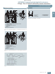
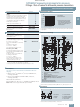
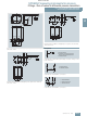
The two-spindle, three-spindle and five-spindle valve manifolds
(7MF9412-1..) are used to shut off the differential pressure lines
and to check the transmitter zero.
The five-spindle valve manifold permits venting on the transmit-
ter side and checking of the transmitter characteristic.
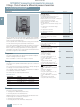
These valve manifolds are preferentially used when mounting in
protective boxes. In addition, they can also be used for wall,
frame or pipe mounting together with the mounting bracket.
Transmitters of the DS series can be operated and read from the
front when using these valve manifolds.
■
Application
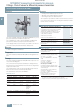
The valve manifolds DN 5 are designed for liquids and vapors
and for installing in protective boxes.
Each is available in a version for oxygen on request
■
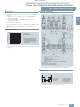
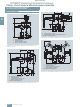
Design
All versions of the spindle manifolds have a process connection
½-14 NPT.
The connection for the pressure transmitter is always designed
as a flange connection to EN 61518, Form A.
The 2-spindle and the 5-spindle valve manifold have in addition
a vent and test connection ¼-18 NPT.
The valves have an external spindle thread.
Materials used
■
Functions
Functions of all valve manifolds:
• Shutting off the differential pressure lines
• Checking the pressure transmitter zero
Additional functions of the 2-spindle and 5-spindle valve mani-
folds through the vent and test connection:
• Venting on the transmitter side
• Checking the pressure transmitter characteristic
Components Material Mat. No.
Housing X 2 CrNiMo 17 13 2 1.4404/316L
Cones X 6 CrNiMoTi 17 12 2 1.4571/316Ti
Spindles X 2 CrNiMo 18 10 1.4404/316L
Head parts X 5 CrNiMo 18 10 1.4401/316
Packings PTFE -
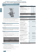
Selection and Ordering data Order No.
Valve manifolds DN 5 for mounting in
protective boxes
7 M F 9 4 1 2 -
7 7
A
for liquids and gases
for flanging to pressure transmitters for
absolute and differential pressure
Material: stainless steel, mat. No: 1.4404/316L
max. working pressure 420 bar
(order accessory set with Order code),
without certificate
• 2-spindle valve manifold with rotatng sleeve
G½
1 B
• 2-spindle valve manifold with flange
connection
1 C
• 3-spindle valve manifold 1 D
• 5-spindle valve manifold 1 E
Accessories
Factory test certificate EN 10204–2.2
7MF9000-8AB
Material acceptance test certificate
EN 10204-3.1
7MF9000-8AD
Selection and Ordering data Order code Order No.
Further designs
1)
Please add "-Z" to Order No. and
specify Order code.
Accessory set to EN
(connection between valve manifold
and pressure transmitter)
for valve manifold 7MF9412–1C.
2x screws
7
/
16
-20 UNF x 2 inch to
ASME B18.2.1; chromized steel
1x O-ring to DIN 3771,
20 x 2.65 - S - FPM90,
max. permissble 420 bar, 120 °C
F32 7MF9412-6CA
2x screws
7
/
16
-20 UNF x
2 inch to ASME B18.2.1; chromized
steel
1x gasket made of PTFE,
max. permissible 420 bar, 80 °C
2)
F35 7MF9412-6DA
for valve manifold 7MF9412–1D and
-1E.
4x screws
7
/
16
-20 UNF x
2 inch to ASME B18.2.1; chromized
steel
2x O-rings to DIN 3771,
20 x 2.65 - S - FPM90,
max. permissble 420 bar, 120 °C
2)
F34 7MF9412-6GA
4x screws
7
/
16
-20 UNF x
2 inch to ASME B18.2.1; chromized
steel
2x flat gaskets made of PTFE,
max. permissible 420 bar, 80 °C
2)
F36 7MF9412-6HA
© Siemens AG 2008