
Marine Instruments User Manual


SITRANS P measuring instruments for pressure
Transmitters for gage pressure for the paper industry
SITRANS P300 and DS III series
with PMC connection – Technical description
2/50
Siemens FI 01 · 2009
2
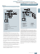
Mode of operation of the FOUNDATION Fieldbus electronics
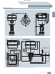
Function diagram of electronics
The bridge output voltage created by the sensor (1, Figure
"Function diagram of electronics") is amplified by the instrument
amplifier (2) and digitized in the analog-to-digital converter (3).
The digital information is evaluated in the microcontroller, its lin-
earity and temperature response corrected, and provided on the
FOUNDATION Fieldbus through an electrically isolated
FOUNDATION Fieldbus Interface (7).
The data specific to the measuring cell, the electronics data, and
the parameter data are stored in the two non-volatile memories
(6). The one memory is coupled to the measuring cell, the other
to the electronics. As the result of this modular design, the elec-
tronics and the measuring cell can be replaced separately from
each other.
Using the three input keys (8) you can parameterize the pressure
transmitter directly at the point of measurement. The input keys
can also be used to control the view of the results, the error mes-
sages and the operating modes on the digital display (9).
The results with status values and diagnostic values are trans-
ferred by cyclic data transmission on the FOUNDATION
Fieldbus. Parameterization data and error messages are trans-
ferred by acyclic data transmission. Special software such as
National Instruments Configurator is required for this.
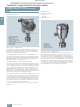
Mode of operation of the measuring cell
Measuring cell for gage pressure with front-flush diaphragm
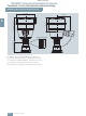
Measuring cell for gage pressure, with front-flush diaphragm, function
diagram
The pressure p
e
is applied through the process connection
(2, Figure "Measuring cell for gage pressure, with front-flush di-
aphragm for paper industry, function diagram") to the measuring
cell (1). This pressure is subsequently transmitted further
through the seal diaphragm (3) and the filling liquid (4) to the sil-
icon pressure sensor (5) whose measuring diaphragm is then
flexed. This changes the resistance of the four piezo-resistors fit-
ted in the diaphragm in a bridge circuit. This change in resis-
tance results in a bridge output voltage proportional to the input
pressure.
Parameterization
Depending on the version, there are a range of options for pa-
rameterizing the pr
essur
e transmitter and for setting or scanning
the parameters.
Parameterization using the input keys (local operation)
With the input keys you can easily set the most important param-
eters without any additional equipment.
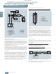
Parameterization using HART communication
Parameterization using HART communication is performed with
a HART communicator or a PC.
Communication between a HART communicator and a pressure
transmitter
When parameterizing with the HART communicator, the connec-
tion is made directly to the 2-wire system.
6
8
p
e
1
2
C
m
M
00000
00
EEPROM
EEPROM
9
6
345 7
10
1 Measuring cell sensor
2 Instrument amplifier
3 Analog-to-digital converter
4Microcontroller
5 Electrical isolation
6One non-volatile memory
each in the measuring cell
and electronics
7FF interface
Sensor
Electronics
Measuring cell
FF
interface
Power
supply
unit
Coup-
ler
Power supply
8 Three input keys
(local operation)
9 Digital display
10 Power supply
p
e
Input variable
p
1
4
3
2
e
5
1 Measuring cell
2Process connection
3 Seal diaphragm
4 Filling liquid
5 Silicon pressure sensor
p
e
Pressure as input variable
+
HART
communicator
230 ... 1100 W
transmitter
SITRANS P
Power supply
© Siemens AG 2008