Technical Instructions Document No. 155-163P25 September 25, 2018 Flowrite™ 599 Series SKB/C Electronic Valve Actuator Proportional Control Description The Flowrite 599 Series SKB/C Electronic Valve Actuator requires a 24 Vac supply and receives a 0 to 10 Vdc or a 4 to 20 mA control signal to proportionally control a valve. This actuator is designed to work with Flowrite 599 Series valves with a 3/4-inch (20 mm) or 1-1/2-inch (40 mm) stroke.
Technical Instructions Document Number 155-163P25 September 25, 2018 Flowrite 599 Series SKB/C Electronic Valve Actuator Proportional Control Warning/Caution Notations Specifications Power Supply Control signal Feedback signal Equipment rating Function WARNING: Personal injury/loss of life may occur if you do not perform a procedure as specified. CAUTION: Equipment damage or loss of data may occur if you do not follow a procedure as specified.
Flowrite 599 Series SKB/C Electronic Valve Actuator Proportional Control Specifications, continued Miscellaneous Accessories Conduit opening Dimensions Weight SKB62U SKC62U Technical Instructions Document Number 155-163P25 September 25, 2018 1/2-inch NPSM See Figure 18 18.9 lbs (8,6 kg) 22 lbs (10,0 kg) Installation instructions are included with each accessory. ASC1.6 Auxiliary switch sends a signal to indicate the valve is in the 0% stroke position. Switching point is fixed at the 0% stroke position.
Technical Instructions Document Number 155-163P25 September 25, 2018 Service Kits Flowrite 599 Series SKB/C Electronic Valve Actuator Proportional Control Circuit board replacement 4 668 5748 8 Manual override kit 4268 5510 8 Plastic wiring compartment cover 4 104 5582 8 Stem retainer kit Contains one stem nut (Figure 7, Item 6) and one stem retainer clip. 2-1/2 and 3-inch valves 599-10048 4, 5, and 6-inch valves 599-10049 Retainer clamp kit 599-10200 Ultraviolet (UV) resistant cable ties (pkg.
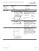
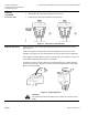
Flowrite 599 Series SKB/C Electronic Valve Actuator Proportional Control Mounting and Installation Technical Instructions Document Number 155-163P25 September 25, 2018 The vertical position is the required position for mounting and the only position for NEMA Type 3R rating with the Weather Shield. Acceptable mounting positions are shown in Figure 7. Figure 7. Acceptable Mounting Positions.
Technical Instructions Document Number 155-163P25 September 25, 2018 Flowrite 599 Series SKB/C Electronic Valve Actuator Proportional Control Start-up, continued To determine the stroke positions 0% and 100% in the valve, calibration is required when the valve/actuator are commissioned for the first time. The actuator must be mechanically connected to a valve and must have a supply voltage of 24 Vac.
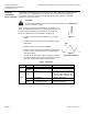
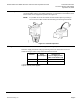
Flowrite 599 Series SKB/C Electronic Valve Actuator Proportional Control Technical Instructions Document Number 155-163P25 September 25, 2018 Start-up, Continued Standard Features 1 2 Figure 10. DIP Switches. DIP Switches (From Left to Right) ON OFF (Factory Settings) 1 Selection of Control Signal 2 Selection of Flow Characteristic 4 to 20 mA Modified* 0 to 10 Vdc Default * Changing the default setting will modify an equal percentage valve to a linear flow characteristic.
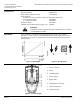
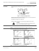
Technical Instructions Document Number 155-163P25 September 25, 2018 Start-up, continued Three-way Valve Flowrite 599 Series SKB/C Electronic Valve Actuator Proportional Control Actuator pressure cylinder moves: • Outward (0 to 1): Valve opens between ports NC and C. • Inward (1 to 0): Valve opens between ports NO and C. Figure 11. Valve Stem Travel Indication. Manual operation Release the crank arm of the manual setting knob located on the top of the actuator. See Figure 12.
Flowrite 599 Series SKB/C Electronic Valve Actuator Proportional Control Automatic operation Technical Instructions Document Number 155-163P25 September 25, 2018 When returning to automatic control, turn the crank arm of the manual setting knob counterclockwise until the red numbers disappear. It is essential that the window is clear and the crank arm is snapped into position. See Figure 13.
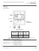
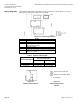
Technical Instructions Document Number 155-163P25 September 25, 2018 Wiring Diagrams Flowrite 599 Series SKB/C Electronic Valve Actuator Proportional Control The position output signal U will switch from 0 to 10 Vdc to 4 to 20 mA when a 4 to 20 mA input signal is selected and used on the Y terminal. Figure 14. Connecting Terminals.
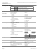
Flowrite 599 Series SKB/C Electronic Valve Actuator Proportional Control Technical Instructions Document Number 155-163P25 September 25, 2018 Dimensions Figure 17. Dimensions of the 599-10065 Weather Shield in Inches (Millimeters). Siemens Industry, Inc.
Technical Instructions Document Number 155-163P25 September 25, 2018 Flowrite 599 Series SKB/C Electronic Valve Actuator Proportional Control Dimensions, Continued Figure 18. Dimensions of SKB/C in Inches (Millimeters). Information in this publication is based on current specifications. The company reserves the right to make changes in specifications and models as design improvements are introduced. Flowrite is a trademark of Siemens Industry, Inc.