
Install Instructions


Document Number: 129-185
Installation Instructions
September 30, 2002
Page 6 of 8
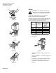
Spring Return SKB82.51U and SKC82.61U
continued
EA0745R1
EARTH GROUND
ISOLATING CLASS 2
TRANSFORMER FOR
24 Vac POWER
120 Vac
21
Y2
Y1
G
1
0
0
NEUT
CONTROLLER
24
Vac
ASZ7.3ASC9.3BCU
3Y1 Y2
4
G
11
Cm1N.O.
5
c1
3
4
5
c2
1000
100%
0%
100%
0%
cba
21
EA0225R3
Figure 27. Spring Return.
Connecting Terminals
G System Potential 24 Vac (+)
21 System Neutral (SN)
Y1 Downward movement of coupling piece (0 to 1)
Y2 Upward movement of coupling piece (1 to 0)
Cm1 Limit switch for 100% stroke
c1 ASC9.3BCU double auxiliary switch
c2 ASC9.3BCU double auxiliary switch
1000 Ω
ASZ7.3 potentiometer
Start-up
Check the wiring for proper connections.
Consult Technical Instructions for detailed
commissioning instructions.
Stroke Calibration
To determine the stroke positions 0% and 100% in the
valve, calibration is required when the valve/actuator
are commissioned for the first time.
For this purpose, the actuator must be mechanically
connected to a valve and must have a supply voltage
of 24 Vac. Repeat the calibration procedure as often as
necessary. See Technical Instructions 155-163P25 for
details.
Normally Closed Valve
Actuator pressure cylinder moves:
• Outward (0 to 1): Valve opens.
• Inward (1 to 0): Valve closes.
Normally Open Valve
Actuator pressure cylinder moves:
• Outward (0 to 1): Valve closes.
• Inward (1 to 0): Valve opens.
Three-Way Valve
Actuator pressure cylinder moves:
• Outward: Valve opens between port NC and C.
• Inward: Valve opens between ports NO and C.
NOTE: The valve body assembly determines the
complete assembly action.
Reference
Technical Instruction Document Number
Flowrite EA599 Series SKB/C
Electronic Valve Actuator
Proportional Control
155-163P25
Flowrite EA599 Series SKB/C
Electronic Valve Actuator 3-
position (Floating) Control
155-171P25
Manual Operation
180°
1
EA0161R1
0
1
1 x 360°= 2
mm
EA0162R1
Figure 28. Manual Operation.
0
1
1
1 x 360°= 2
mm
EA0160R1
2
Figure 29. Return to Automatic Operation.