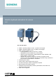
ACVATIX™ Electro-hydraulic actuators for valves SKD.. with a 20 mm stroke ● ● ● ● ● ● ● ● ● CM1N4561en 2021-06-21 SKD32.. Operating voltage AC 230 V, 3-position control signal SKD82.. Operating voltage AC 24 V, 3-position control signal SKD6.. Operating voltage AC 24 V – Control signal DC 0...10 V, 4...20 mA or 0...
Use For the operation of Siemens 2-port and 3-port valves of the types VVF.., VVG.., VXF.. and VXG.. with a 20 mm stroke as control and safety shut-off valves in heating, ventilation and air conditioning plants.
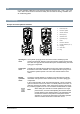
Automatic operation mode For automatic operation, turn the manual adjuster [1] counter-clockwise to the end stop. The pressure cylinder moves upward to the 0 % stroke position of the valve. The red indicator marked “MAN” is no longer visible. Minimal volumetric flow The actuator can be manually adjusted to a stroke position > 0%, allowing its use in applications requiring a constant minimal volumetric flow. The actuator is controlled by a 3-position signal either via terminals Y1 or Y2 SKD32..
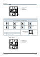
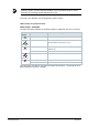
Electronics SKD60 1) 1) 1 Connection terminals 2 DIL switches 3 LED status indication 4 Stroke calibration From version ..L onward DIL switches Direction of operation Fail-in-place (behaviour in case of control signal loss) ** Positioning signal Y Flow characteristic Positioning feedback U ON Reverse acting Stops at current position DC 4...20 mA lin = linear OFF * Direct acting Closes DC 0...
DIL switches Positioning signal Y Flow characteristic Positioning feedback U ON DC 4...20 mA lin = linear OFF * DC 0...
SKD62/MO The Modbus converter is designed for analog control at 0...10 V. Keep the analog signal setting on the actuator as is (switch 1 to OFF); adjustment not permitted. The actuators are factory configured for equal-percentage characteristic. DIL switch (internal actuator characteristic changeover) to "log" (switch 2 to OFF). Functions Notstellfunktion The SKD32.21, SKD32.51, SKD82.51.. and SKD62..
The LED on the SKD62/MO cable adapter flashes red during the calibration, as the positioning signal Y and the positioning feedback U do not correspond anymore. This is interpreted as a blockage and thus indicated as an error. If necessary, the calibration can be repeated any number of times. LED indication of operational status SKD60, SKD62.., SKD62/MO The dual-colored LED indicating the operational status is visible when the cover is removed.
Override control Z SKD60, SKD62..
Stroke limit control and sequence control SKD62UA Setting the stroke limit control Setting the sequence control The rotary switches LO and UP can be used to apply a lower and upper limit to the stroke in increments of 3%, up to a maximum of 45%. The rotary switches LO and UP can be used to determine the start point or the operating range of a sequence.
Type summary Operating voltage Type SKD32.21 Positioning signal 1) SKD32.50 1) AC 230 V SKD32.51 1) SKD82.50 1) - 3-position SKD82.50U 2) SKD82.51 1) SKD82.51U 2) SKD60 1), 3) SKD60U 2) Standard electronics SKD62 1) AC 24 V SKD62U 2) SKD62UA 2), 4) SKD62/MO 2) Standardelektronik Positioning time Function Time yes 8s - - yes 8s - - yes 8s - - yes 15 s DC 0...10 V 4...20 mA 0...
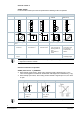
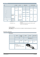
SKD32.. SKD82.. ASC9.3 ASZ7.3 ASK50 Double auxiliary switch Potentiometer Mechanical stroke inverter Adjustable switching points 0…1000 Ω 0% actuator stroke corresponds to 100% valve stroke Mount between valve and actuator Note: ASZ7.3 For the combination SIMATIC S5/S7 and use of positioning feedback, we recommend actuators with DC 0...9.8 V feedback signals. The signal peaks that occur in the potentiometer ASZ7.3 may result in error messages on Siemens SIMATIC.
Spare parts Actuator Hand control 1) Cover Control unit SKD32.21 SKD32.50 SKD32.51 SKD82.50 - SKD82.50U SKD82.51 SKD82.51U 410456348 426855048 SKD60 466857598 SKD60U SKD62 466857488 SKD62U SKD62UA 466857518 SKD62/MO 466857488 1) Hand control, blue with mechanical parts Equipment combinations 2-port valves VV.. (control or safety shut-off valves) Valve type DN PN class kvs Data sheet [m3/h] VVF21.. 1) 25...80 VVF22.. 15...80 VVF32.. Flannged VVF42.. VVF52.. 50 16 15...
3-port valves VX.. (control valves for “mixing” and “distribution”) Valve type DN PN class kvs Data sheet [m3/h] VXF21.. 1) 25...80 VXF22.. VXF32.. 15...80 VXF41.. 1) Flansch 15...50 VXF42.. 10 16 15...80 VXF53.. 25 VXF61.. 15...50 VXF63.. VXG41.. 1.9...100 N4410 N4401 2.5...100 VXF31.. 1) VXF40.. 1) 6 Gewinde 40 16 N4420 1.6...100 N4402 1.9...100 N4430 1.9...31 N4440 1.6...100 N4403 1.6...40 N4405 1.9...31 N4482 0.2...36 A6V11459527 1.6...
Notes Sicherheit CAUTION National safety regulations Failure to comply with national safety regulations may result in personal injury and property damage. ● Observe national provisions and comply with the appropriate safety regulations. WARNING Tensioned spring return Opening the actuator housing can release the highly tensioned return spring, which can cause flying parts and injuries. ● Do not open the actuator housing.
Engineering Der elektrische Anschluss ist gemäss den örtlichen Vorschriften für Elektroinstallationen und dem Kapitel Anschlussschaltpläne [➙ 26] durchzuführen. NOTE Using a safety limiter Failure to comply with applicable regulations for cable insulation may result in the suspension of the safety limiter function. ● Compliance with all applicable regulations for cable insulation must be ensured by the plant operator.
Mounting Mounting instructions 74 319 0324 0 for fitting the actuator to the valve and A5W00027551 for SKD62/MO are enclosed in the actuator packaging. The instructions for accessories are enclosed with the accessories themselves (see Product documentation [➙ 13]). Mounting positions Commissioning When commissioning the system, check the wiring and functions, and set any auxiliary switches and potentiometers as necessary, or check the existing settings.
Maintenance The actuators are maintenance-free. When servicing the control device: WARNING Verbrennungsgefahr durch heisse Antriebskonsole The actuator brackets on heating plants can also become hot from the contact with the hot valve during operation. The temperature of the actuator bracket can reach 100 °C. When servicing the actuator: ● Switch off both pump and operating voltage. ● Close the main shutoff valve in the piping. ● Release pressure in the pipes and allow them to cool off completely.
Disposal WARNUNG Tensioned spring return Opening the actuator housing can release the highly tensioned return spring, which can cause flying parts and injuries. ● Do not open the actuator housing. The device is considered an electronic device for disposal in accordance with the European Guidelines and may not be disposed of as domestic garbage. ● Dispose of the device through channels provided for this purpose. ● Comply with all local and currently applicable laws and regulations.
Technical data Power supply Operating voltage SKD32.. AC 230 V ± 15 % SKD82.. SKD6.. AC 24 V ± 20 % (SELV/PELV) SKD62/MO Frequency 50 / 60 Hz Maximum power consumption at 50 Hz SKD32.21 16 VA / 12 W SKD32.50 11 VA / 8 W SKD32.51 17 VA / 12 W SKD82.50, SKD82.50U 9 VA / 7 W SKD82.51, SKD82.51U 14 VA / 10 W SKD60.. 10 VA / 8 W SKD62.. 14 VA / 10 W External supply cable fuse SKD32.. Min. 0.5 A, slow Max. 6 A slow SKD82.. Min. 1 A, slow SKD6.. Max.
Signal inputs / signal outputs Positioning signal Y SK6.. Input impedance DC 0…10 V 100 kΩ DC 4…20 mA 240 Ω Signal resolution <1% Hysteresis 1% Override control Z SK6.. Resistor 1000 Ω Z not connected, priority terminal Y No function Z connected directly to G Max. stroke 100 % Z connected directly to G0 Min. stroke 0 % Z connected to M via 0...1000 Ω Stroke proportional to R Position feedback U SK6.. Load impedance DC 0…9,8 V > 10 kΩ DC 4…19.
Electrical connections and connecting cable Wire cross-sectional area 0.5...2.5 mm2, AWG 21...14 3) Cable entries 4 x M20 (∅ 20.5 mm) With knockouts for standard ½" conduit connectors (∅ 21.5 mm) SKD62/MO Mit Ausbrechöffnungen für ½" Schlauchverbindungen (∅ 21,5 mm) Fixed connection cable Cable length 0.9 m Number of cores 5 x 0.
Dimensions / weight Dimensions See Dimensions [➙ 30] Weight SKD32.21 3.65 kg SKD32.50 3.60 kg SKD32.51 3.65 kg SKD82.50 3.60 kg SKD82.50U 3.85 kg SKD82.51 3.65 kg SKD82.51U 3.90 kg SKD60 SKD62, SKD62/MO External Modbus converter SKD62U SKD62UA Stroke inverter ASK50 3.60 kg 0.15 kg 3.85 kg 1.10 kg Materials Housing Die-cast aluminium Bracket Housing box Plastic Manual adjuster Accessories Auxiliary switch ASC1.6 SKD6.. Switching capacity AC 24 V, 10 mA....
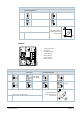
Connection diagrams Internal diagrams SKD32.. SKD32.21 SKD32.50 SKD32.51 AC 230 V 3-position Cm1 End switch n Solenoid valve for spring-return c1, c2 ASC9.3 double auxiliary switch a, b, c ASZ7.3 potentionmeter Y1 Positioning signal „open“ Y2 Positioning signal „close“ 21 Spring-return function N Neutral conductor SKD82.. SKD82.51 SKD82.50 AC 24 V 3-position Siemens Smart Infrastructure Cm1 End switch n Solenoid valve for spring-return c1, c2 ASC9.
SKD6.. SKD60, SKD62 SKD62U, SKD62UA AC 24 V DC 0...10 V 4...20 mA 0...
Connection terminals SKD6.. AC 24 V DC 0...10 V 4...20 mA 0...1000 Ω System neutral (SN) System potential (SP) Positioning signal DC 0...10 (30) V or DC 4...20 mA Measuring neutral (= G0) Position indication DC 0...10 V oder DC 4...20 mA Override control (Functions [➙ 8]) SKD62/MO AC 24 V Modbus RTU Connection cable System neutral (SN) Black System potential (SP) Red Reference line (Modbus RTU) Violet Bus + (Modbus RTU) Gray Bus - (Modbus RTU) Pink Auxiliary switch ASC1.
Connection diagrams SKD32.. SKD32.21 SKD32.50 SKD32.51 AC 230 V 3-position 26 Siemens Smart Infrastructure F1 Safety limiter (e.g.
SKD82.. SKD82.51, SKD82.51U SKD82.50, SKD82.50U AC 24 V 3-position F1 Siemens Smart Infrastructure Safety limiter (e.g.
SKD6.. SKD60 DC 0...10 V AC 24 V 4...20 mA 0...1000 Ω SKD62, SKD62U, SKD62UA DC 0...10 V AC 24 V 4...20 mA 0...1000 Ω Y1 Actuator F3 Temperature detector N1 Controller F4 Frost protection monitor with 0...1000 Ω signal output, e.g. QAF21.. or QAF61.. (only SKB62UA) *) F1 Safety limiter (e.g.
SKD62/MO AC 24 V Modbus RTU A Actuator N1 Controller G System potential G0 System neutral REF Reference line (Modbus RTU) + Bus + (Modbus RTU) - Bus - (Modbus RTU) HINWEIS Using safety limiter F1 When using the safety limiter F1, ensure that no mistakes may occur on cable insulation that may cancel out the temperature limiter function (applies to both 230 V as well as 24 V types). ● For SN earthing (e.g. PELV) comply under all circumstances with the note above.
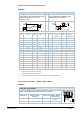
Dimensions Actuator All dimensions in mm * Height of actuator from plate without stroke inverter ASK50 = 300 mm Height of actuator from plate with stroke inverter ASK50 = 357 mm ** SKD..U: with knockouts for standard ½" conduit connectors (∅ 21.5 mm) > 100 mm, um clearance form ceiling or wall for mounting > 200 mm, connection, operation, maintenance, etc.
External Modbus converter All dimensions in mm X Siemens Smart Infrastructure 250 mm 31 CM1N4561en 2021-06-21
Revision numbers Type Valid from rev. no. Type Valid from rev. no. SKD32.50 ..F SKD62 ..H SKD32.51 ..F SKD62U ..H SKD32.21 ..F SKD60 ..H SKD82.50 ..F SKD62UA ..H SKD82.50U ..F SKD62/MO ..I SKD82.51 ..F SKD82.51U ..F Issued by Siemens Switzerland Ltd Smart Infrastructure Global Headquarters Theilerstrasse 1a CH-6300 Zug Tel. +41 58 724 2424 www.siemens.