
Data Sheet for Product


2
Siemens CM1N4561en
Smart Infrastructure 2021-06-21
Use
For the operation of Siemens 2-port and 3-port valves of the types VVF.., VVG.., VXF.. and
VXG.. with a 20 mm stroke as control and safety shut-off valves in heating, ventilation and
air conditioning plants.
Technical design
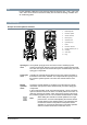
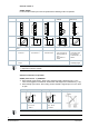
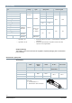
Principle of electro-hydraulic actuators
1 Manual adjuster
2 Pressure cylinder
3 Suction chamber
4 Return spring
5 Solenoid valve
6 Hydraulic pump
7 Piston
8 Pressure chamber
9 Position indicator (0 to 1)
10 Coupling
11 Valve stem
12 Plug
Valve closed Valve opened
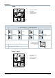
Opening the
valve
The hydraulic pump [6] forces oil from the suction chamber [3] to the
pressure chamber [8], thereby moving the pressure cylinder [2] downwards.
The valve stem [11] retracts and the valve opens. Simultaneously, the return
spring [4] is compressed.
Closing the
valve
Activating the solenoid valve [5] allows the oil in the pressure chamber to
flow back into the suction chamber. The compressed return spring moves
the pressure cylinder upwards. The valve stem extends and the valve
closes.
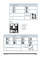
Manual
operation
mode
Turning the manual adjuster [1] clockwise moves the pressure cylinder
downwards and opens the valve. Simultaneously, the return spring [4] is
compressed.
In the manual operation mode, the positioning signals Y and Z can further
open the valve but cannot move to the 0 % stroke position of the valve. To
retain the manually set position, switch off the power supply or disconnect
the positioning signals Y and Z. The red indicator marked “MAN” is visible.
Note:
When setting the controller to manual operation for a longer
period of time, we recommend adjusting the actuator with the
manual adjuster to the desired position. This guarantees that
the actuator remains in this position for that period of time.
Attention: Do not forget to switch back to automatic operation
after the controller is set back to automatic control.