
Data Sheet for Product


3
Siemens CM1N4561en
Smart Infrastructure 2021-06-21
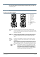
Automatic
operation
mode
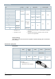
For automatic operation, turn the manual adjuster [1] counter-clockwise to
the end stop. The pressure cylinder moves upward to the 0 % stroke
position of the valve. The red indicator marked “MAN” is no longer visible.
Minimal
volumetric
flow
The actuator can be manually adjusted to a stroke position > 0%, allowing
its use in applications requiring a constant minimal volumetric flow.
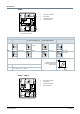
SKD32..
SKD82..
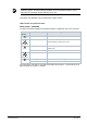
3-position
control signal
The actuator is controlled by a 3-position signal either via terminals Y1 or Y2
and generates the desired stroke, which is transferred to the valve stem:
● Voltage on Y1: Piston extends Valve opens
● Voltage on n Y2: Piston retracts Valve closes
● No voltage on Y1 and Y2:
Piston and valve stem remain in the
respective position
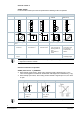
SKD62..
SKD60
Y positioning
signal
DC 0...10 V
and/or
0...1000 Ω,
DC 4...20 mA
The actuator is either controlled via terminal Y or override control Z. The
positioning signals generate the desired stroke by means of the above
described principle of operation, which is transferred to the valve stem:
● Signal Y increasing: Piston extends Valve opens
● Signal Y decreasing: Piston retracts Valve closes
● Signal Y constant:
Piston and valve stem remain in the
respective position
● Override control Z: See Functions [➙ 8]
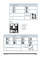
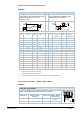
Frost
protection
monitor
Frost
protection
thermostat
A frost protection thermostat can be connected to the SKD6.. actuator.
The added signals from the frost protection monitors QAF21.. and QAF61..
require the use of SKD62UA actuators. Notes on special programming of
the electronics are described under Electronics [➙ 5].
Connection diagrams for operation with frost protection thermostat or frost
protection monitor can be found under Connection diagrams [➙ 26].