
Data Sheet for Product


9
Siemens CM1N4561en
Smart Infrastructure 2021-06-21
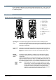
Stroke limit control and sequence control
SKD62UA
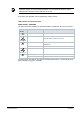
Setting the stroke limit control Setting the sequence control
The rotary switches LO and UP can be
used to apply a lower and upper limit to the
stroke in increments of 3%, up to a
maximum of 45%.
The rotary switches LO and UP can be
used to determine the start point or the
operating range of a sequence.
Position
of LO
Lower stroke
limit
Position
of UP
Upper stroke
limit
Position
of LO
Sequence
control
start point
Position
of UP
Sequence
control
operating range
0 0 % 0 100 % 0 0 V 0 10 V
1 3 % 1 97 % 1 1 V 1 10 V *
2 6 % 2 94 % 2 2 V 2 10 V **
3 9 % 3 91 % 3 3 V 3 3 V ***
4 12 % 4 88 % 4 4 V 4 4 V
5 15 % 5 85 % 5 5 V 5 5 V
6 18 % 6 82 % 6 6 V 6 6 V
7 21 % 7 79 % 7 7 V 7 7 V
8 24 % 8 76 % 8 8 V 8 8 V
9 27 % 9 73 % 9 9 V 9 9 V
A 30 % A 70 % A 10 V A 10 V
B 33 % B 67 % B 11 V B 11 V
C 36 % C 64 % C 12 V C 12 V
D 39 % D 61 % D 13 V D 13 V
E 42 % E 58 % E 14 V E 14 V
F 45 % F 55 % F 15 V F 15 V
* Operating range of QAF21.. (see below)
** Operating range of QAF61.. (see below)
*** The smallest adjustment possible is 3 V; control with 0...30 V is only possible via Y.
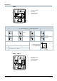
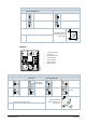
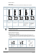
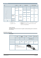
Stroke control with QAF21.. / QAF61.. signal addition
SKD62UA
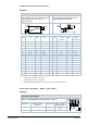
Setting the signal addition
The operating range of the frost protection monitor QAF21.. or
QAF61.. can be defined with rotary switches LO and UP.
Position of LO
Sequence control
start point
Position of UP
QAF21.. / QAF61..
operating range
0 → 1 QAF21..
0 → 2 QAF61..