Technical Instructions Document No. 7643 SKPx5 Series SKPx5.xxxUx July 25, 2017 SKPx5.xxxUx Gas Valve Actuator with Safety Shutoff Function SKP15.xxxUx SKP25.xxxUx SKP55.xxxUx SKP75.xxxUx ISO 9001 and 14000 REGISTERED FIRM Only when assembled to series VGxxx.xxxU gas valves General description SKPx5.xxxUx electro‐hydraulic actuators are used in combination with VGxxx.
Technical Instructions Document Number CC1N7643us July 25, 2017 Application SKPx5.xxxUx Electro‐hydraulic actuators All SKPx5.xxxUx electro‐hydraulic actuators combine with VGxxx.xxxU gas valves to provide safety shut‐off control for industrial and commercial burner applications. VGxxx.xxxU or VRD40.xxxU gas valve bodies to be ordered separately. Type of valve Medium Data Sheet VGG10.xxxU Natural gas, air N7636us VGD20.xxxU VGD4x.xxxU Natural gas, air N7631us VRD40.
SKPx5.xxxUx Electro‐hydraulic actuators Features SKPx5.xxxUx Technical Instructions Document Number CC1N7643us July 25, 2017 • UL listed, FM approved, CSA certified, IRI approval, and ISO 9001 certified. European, Australian and Japanese approved versions available. • Proof of Closure with Over Travel (POC) option. • Optional NEMA 4 protection. • Visual position indication. • "Power on" indication light. • Quick connect wiring terminals. • Optional adjustable auxiliary switch.
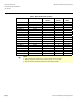
Technical Instructions Document Number CC1N7643us July 25, 2017 SKPx5.xxxUx Electro‐hydraulic actuators Product Numbers Table 1. SKPx5.xxxUx model numbers Product Number SKP15.011U1 SKP15.011U2 SKP15.012U1 SKP15.012U2 SKP15.013U1 SKP25.011U1 SKP25.012U1 SKP25.012U2 SKP25.013U1 SKP25.411U1 1 SKP25.611U1 2 SKP55.011U1 SKP55.012U1 SKP55.012U2 SKP55.013U1 SKP75.011U1 SKP75.012U1 SKP75.012U2 SKP75.
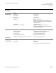
SKPx5.xxxUx Electro‐hydraulic actuators Technical Instructions Document Number CC1N7643us July 25, 2017 Accessories AGA22 Yellow setpoint spring for 6” to 48” w.c. (1.5 to 10 psi for SKP25.411U1) AGA23 Red setpoint spring for 40” to 100” w.c. (8.5 to 20 psi for SKP25.411U1) AGA25.2 Damping orifice for mounting into vent connection of SKP25.0xxUx or SKP25.4xxUx models AGA28 Black bias spring to install if SKP25.0xxUx for ‐0.4" to 0.4" w.c.
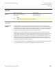
Technical Instructions Document Number CC1N7643us July 25, 2017 SKPx5.xxxUx Electro‐hydraulic actuators Specifications Agency approvals As safety shut‐off valve UL/429, FM/7400, ANSI Z21.21/CSA6.5 C/I Agency marks apply only for SKPx5.xxxUx actuators with VGxxx.xxxU series gas valve bodies. SKP25.xxxUx, SKP55.xxxUx and SKP75.xxxUx As a pressure regulator ANSI Z21.18/CSA 6.
SKPx5.xxxUx Electro‐hydraulic actuators Technical Instructions Document Number CC1N7643us July 25, 2017 Specifications Continued Physical characteristics Weight SKP15.xxxUx SKP25.xxxUx SKP55.xxxUx SKP75.xxxUx Enclosure Dimensions Specification for valve bodies 2.4 lb (1.1 kg) 3.5 lb (1.6 kg) 4.2 lb (1.9 kg) 5.1 lb (2.3 kg) NEMA 1, 2, 5, and 12 NEMA 3, 3R, and 4 with optional AGA66 sealing gasket (mounted with VGG10.xxxU / VGDxx.xxxU / VRD40.xxxU valves) See Figures 12...
Technical Instructions Document Number CC1N7643us July 25, 2017 SKPx5.xxxUx Electro‐hydraulic actuators Specifications Continued Operation / installation Outlet pressure spring range 0" to 8.5" w.c. (standard, unpainted spring, AGA29) SKP25.xxxUx for SKP25.0xxUx models 6" to 48" w.c. (yellow spring, AGA22) 40" to 100" w.c. (red spring, AGA23) 1.5 to 10 psi (standard, yellow spring, AGA22) 8.5 to 20 psi (red spring, AGA23) ± 0.4" w.c. bias (black spring AGA28) 0.4" to – 4" w.c. bias 20 psi for SKP25.
SKPx5.xxxUx Electro‐hydraulic actuators Technical Instructions Document Number CC1N7643us July 25, 2017 Specifications Continued Auxiliary features Proof of closure switch Setting range of auxiliary switch Switch rating Non‐adjustable 40% to 100% of stroke 4 A (2 A, cos = 0.
Technical Instructions Document Number CC1N7643us July 25, 2017 SKPx5.xxxUx Electro‐hydraulic actuators 7643z56/0916 7643z55/0916 Operation continued Figure 1. SKP15.xxxUx operation Figure 2. SKP25.xxxUx operation M AIR M PC 3 PA 5 PG 1 7643z58/0916 7643z57/0916 M 0.4 9 + PG 4 Figure 3. SKP55.xxxUx operation Page 10 Figure 4. SKP75.
SKPx5.xxxUx Electro‐hydraulic actuators Technical Instructions Document Number CC1N7643us July 25, 2017 Operation continued (see Figure 2) Regulating function SKP25.xxxUx The outlet gas pressure sensing line is connected to the pressure regulator housing. The outlet pressure acts on the regulator diaphragm. The diaphragm is opposed by an adjustable setpoint spring force, which represents the desired gas pressure value.
Technical Instructions Document Number CC1N7643us July 25, 2017 SKPx5.xxxUx Electro‐hydraulic actuators Operation continued (see Figure 3) SKP55.xxxUx During the burner pre‐purge period, when the gas valve is closed, only the air pressure difference acts on the regulator causing the air diaphragm to move and close the regulating hydraulic bypass valve. When the actuator is powered, the gas valve begins to open.
SKPx5.xxxUx Electro‐hydraulic actuators Technical Instructions Document Number CC1N7643us July 25, 2017 Operation continued (see Figure 4) SKP75.xxxUx During the burner pre‐purge period, when the gas valve is closed, only the air pressure acts on the regulator. This causes the air diaphragm to move to the left and close the regulating hydraulic bypass valve. When the actuator is powered, the gas valve begins to open.
Technical Instructions Document Number CC1N7643us July 25, 2017 SKPx5.xxxUx Electro‐hydraulic actuators Installation WARNING: • Personal injury or loss of life may occur if procedures are not followed as specified. • All installations must be performed by qualified personnel only. • Do not pull the actuator shaft. • The AGA66 gasket must be installed between the actuator and the gas valve body to provide NEMA 3, 3R, and 4 protection rating for VGG10.xxxU and VGDxx.
SKPx5.xxxUx Electro‐hydraulic actuators Technical Instructions Document Number CC1N7643us July 25, 2017 Installation continued SKP55.xxxUx The pressure connection pipes should be as short as possible to allow the regulator to react to sudden changes. In cases where it is not possible to install an orifice in the air line, (e.g., lack of available air pressure) the SKP55.
Technical Instructions Document Number CC1N7643us July 25, 2017 SKPx5.xxxUx Electro‐hydraulic actuators Installation continued SKP75.xxxUx • Air proving safety device normally required to guarantee minimum airflow must also be provided when using the SKP75.xxxUx. • The sensing line for the combustion chamber pressure (if needed) must be installed so that condensing flue gases cannot enter into the regulator but run back into the combustion chamber. If necessary, a water separator must be installed.
SKPx5.xxxUx Electro‐hydraulic actuators Technical Instructions Document Number CC1N7643us July 25, 2017 Start‐up Regulator WARNING: When firing at maximum burner capacity, ensure that the SKPx5.xxxUx / VGxxx.xxxU is not in the fully open position. If this is the case, either the gas valve is sized too small or the gas supply pressure is too low. SKP25.xxxUx The gas outlet pressure setpoint adjustment screw is located in the center of the regulator cover. The SKP25.
Technical Instructions Document Number CC1N7643us July 25, 2017 SKPx5.xxxUx Electro‐hydraulic actuators Start‐up continued SKP55.xxxUx 1. The setting screw 1 on the SKP55.xxxUx is factory‐adjusted so that the air/gas ratio curve intersects the zero point (no bias). If required, on‐site adjustment may be achieved as follows: • Turn setting screw 1 counterclockwise until spring becomes completely loose. • Shut off gas supply upstream of the SKP55.xxxUx actuator.
SKPx5.xxxUx Electro‐hydraulic actuators Technical Instructions Document Number CC1N7643us July 25, 2017 Start‐up continued SKP75.xxxUx The pressure ratio and bias adjustment screws are located on top of the regulator under a sealable cover plate. The actual settings can be seen through windows on each side of the regulator. NOTE: The burner capacity is controlled by the position of the air damper.
Technical Instructions Document Number CC1N7643us July 25, 2017 SKPx5.xxxUx Electro‐hydraulic actuators P1 Pressure Reducing T‐ Fitting AGA78 130 120 110 100 90 70 D1 60 D1 50 = 5 1, m m ,5 =1 = 2 2 ;D mm m m m ,7 =1 m 7643d02/0503 80 2 ;D 40 30 20 10 10 Figure 9. AGA78 Operation. Function 20 30 P2 Figure 10. AGA78 Adjustments. The air is blown out continuously into the atmosphere through the restrictor D2. The air undergoes a drop in pressure across the restrictor D1.
SKPx5.xxxUx Electro‐hydraulic actuators Terminal designations Technical Instructions Document Number CC1N7643us July 25, 2017 SKPx5.011U SKPx5.012U SKPx5.013U 4A/250V 4A/250V 7643z67us/1116 7643z66us/0217 7643z65us/0217 Figure 11. Terminal designations Dimensions Dimensions in inches; millimeters [mm] in brackets 7.40 [188] SKP15.xxxUx 3.15 [80] 3.82 [97] 1/2"-14 NPSM 7643m39us/1016 2.16 [55] 3.43 square [87] 3.20 [81] Figure 12. SKP15.
Technical Instructions Document Number CC1N7643us July 25, 2017 SKPx5.xxxUx Electro‐hydraulic actuators Dimensions continued Dimensions in inches; millimeters [mm] in brackets SKP25.0xxUx 3.78 [96] 1/4" Rp Female 1.30 [33] 1.03 [26] Pressure test port 0.35" [8.5] o.d. 1/4"-18 NPT Female 7.95 [202] 6.61 [168] 7.87 [200] 8.70 [221] 1.14 [36] 1/2"-14 NPSM 3.82 [97] 3.15 [80] 7643m40us/0717 3.43 Square [87] 2.16 [55] 3.20 [81] Figure 13. SKP25.
SKPx5.xxxUx Electro‐hydraulic actuators Technical Instructions Document Number CC1N7643us July 25, 2017 Dimensions continued Dimensions in inches; millimeters [mm] in brackets SKP25.4xxUx 2.84 [72] 1/4" Female 1.30 [33] Pressure test port 0.35" [8.5] o.d. 1/4"-18 NPT Female 7.95 [202] 6.61 [168] 8.15 [207] 8.70 [221] 0.99 [25] 1/2"-14 NPSM 3.82 [97] 3.15 [80] 7643m41us/1016 3.43 Square [87] 3.20 [81] 4.14 [105] 2.16 [55] Figure 14. SKP25.
Technical Instructions Document Number CC1N7643us July 25, 2017 SKPx5.xxxUx Electro‐hydraulic actuators Dimensions continued Dimensions in inches; millimeters [mm] in brackets SKP55.xxxUx 3.66 [93] 2.28 [58] 1,4" Female 1.30 [33] 0.98 [25] 0.98 [25] 1/4"-18 NPT Female 0.98 [25] 1/4"-18 NPT Female Pressure test port 0.35" [8.5] o.d. 7.95 [202] 6.61 [168] 8.15 [207] 9.17 [233] 1.41 [36] 1/2"-14 NPSM 3.82 [97] 3.15 [80] 7643m42us/1016 2.16 [55] 3.43 Square [87] 3.20 [81] 4.
SKPx5.xxxUx Electro‐hydraulic actuators Technical Instructions Document Number CC1N7643us July 25, 2017 Dimensions continued Dimensions in inches; millimeters [mm] in brackets SKP75.xxxUx 4.96 [126] 1.41 [36] 1.10 [28] Pressure test ports (QTY 2) 0.35" [8.5] o.d. 1/4"-18 NPT Female (QTY 2) 6.61 [168] 7.36 [187] 7.95 [202] 9.41 [239] 9.49 [241] 10.55 [268] 1/4"-18 Female 2.32 [59] 2.09 [53) 1.30 [33] 0.98 [25] 3.15 [80] 3.82 [97] 1/2"-14 NPSM 7643m43us/1016 3.43 Square [87] 2.16 [55] 3.