SPCK 420/421 LCD-Keypad User Guide Version 3.1 A6V10209178 26.09.
Copyright Copyright Technical specifications and availability subject to change without notice. © Copyright Siemens AB We reserve all rights in this document and in the subject thereof.
Table of contents 1 Security ............................................................................................................... 4 1.1 Target group ......................................................................................................... 4 1.2 General safety instructions ................................................................................... 4 1.2.1 General information .............................................................................. 4 1.2.
1 Security Target group 1 Security 1.1 Target group The instructions in this documentation are directed at the following target group: 1.2 1.2.1 Target readers Qualification Activity Condition of the product End user Instruction by technical specialists is necessary. Performs only the procedures for proper operation of the product. The product is installed and configured. General safety instructions General information Keep this document for later reference.
Security Meaning of written warning notices 1.3 1.4 1 Meaning of written warning notices Signal Word Type of Risk DANGER Danger of death or severe bodily harm. WARNING Possible danger of death or severe bodily harm. CAUTION Danger of minor bodily injury or property damage IMPORTANT Danger of malfunctions Meaning of hazard symbols WARNING Warning of hazard area WARNING Warning of dangerous electrical voltage 5 Siemens AB Security Products A6V10209178 26.09.
2 Directives and standards EU directives 2 Directives and standards 2.1 EU directives This product complies with the requirements of the European Directives 2004/108/EC “Directive of Electromagnetic Compatibility” and 2006/95/EC “Low Voltage Directive”. The EU declaration of conformity is available to the responsible agencies at: Siemens AB Building Technologies Division International Headquarters Fire Safety & Security Products Postal Address P.O.
Introduction 3 3 Introduction The keypad is a wall-mounted interface that allows: Engineers to program the system through the Engineer Programming menus (password protected) and to set/unset the system; a user can control the system on a day-to-day basis. Users to enter User Programming menus (password protected), and to perform operational procedures (set/unset) on the system. (Please refer to the SPCK420/421 User Manual for more details of user programming.
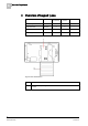
3 Introduction 2 1 1 5 4 ghi 6 7 pqrs ok 7 2 abc 5 jkl 8 3 def 6 mno 9 tuv wxyz 0 # 8 3 4 3 LCD keypad 1 LCD display The keypad display (2 lines x 16 characters) shows all alert and warning messages and provides a visual interface for programming the system (engineer programming only). The display can be adjusted for contrast and under which conditions the backlight comes on.
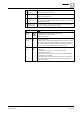
Introduction 3 5 LED status indicators The LED status indicators provide information on the current status of the system as detailed in the table below. 6 Soft function keys The left and right soft function keys are context sensitive keys to navigate through menus/programming. 7 Proximity device receiver area If the keypad has been fitted with a proximity device receiver (see page [➙ 10]), users should present the Portable ACE Fob to within 1 cm of this area to SET/UNSET the system.
4 Overview of keypad types 4 Overview of keypad types Keypad type Model no. Basic Functionality Proximity Detection Audio Standard Keypad SPCK420 ✓ - - Keypad with PACE SPCK421 ✓ ✓ - Comfort Keypad SPCK620 ✓ Comfort Keypad with Audio/CR SPCK623 ✓ ✓ ✓ Keypad Label SPCK420/421 1 Label on inside of Keypad 2 Pull-down label for providing installer details. Fill in all relevant details when installation is complete. 10 Siemens AB Security Products A6V10209178 26.09.
Using the keypad interface 5 5 Using the keypad interface 9 8 7 1 6 2 ok 5 3 4 Keypad display 1 RIGHT SOFT KEY This key is used to select the option presented on the right side of the bottom line display.
5 Using the keypad interface Possible values are: → EXIT to exit programming → BACK to return to previous menu 8 BOTTOM LINE OF DISPLAY 9 TOP LINE OF DISPLAY In the IDLE state, this line is blank. In Programming mode, this line displays options available to the user. These options align over the left and right soft keys for selection as required. In the IDLE state, displays the current date and time.
Using the keypad interface – XBUS fuse fault – XBUS tamper fault – XBUS antenna fault – XBUS wireless jamming – XBUS panic – XBUS fire – XBUS medical – XBUS Power supply link – Engineer restore Required 5 System information – Soaked zones – Open zones – Area state – Low battery (sensor) – Sensor lost – WPA Low battery – WPA lost – WPA Test overdue – Camera offline – Reboot – Hardware fault – Aux over current – Battery low 13 Siemens AB Security Products A6V1
6 User programming via the keypad Setting and unsetting the system 6 User programming via the keypad User programming options are available using the LCD and Comfort Keypads. Menus and options available on the intrusion control panel is programmed by the installation engineer. If users cannot see an option described in this manual, they do not have rights to access that functionality. To access user programming: 1. Enter a valid User PIN. 2.
User programming via the keypad Setting and unsetting the system 6.1.1 6 1 UNSET Performs an Unset on the system. If multiple areas are defined then each area is presented in a sub-menu. For a single area system this option is only presented when the system is Set. 2 FULLSET Performs a Fullset on the system. If multiple areas are defined then each area is presented in a sub-menu. For a single area system this option is only presented when the system is Unset.
6 User programming via the keypad Setting and unsetting the system The system fails to set if there is an open or fault condition detected on an alarm zone when the FULLSET or PARTSET A/B option is selected. The keypad displays the zone number and description. To set the system, locate the zone and close or fix the fault. Repeat the FULLSET or PARTSET A/B operation. 6.1.
User programming via the keypad Setting and unsetting the system 6 closed again or a severed X-BUS connection re-established. The SPC system does NOT provide the Restore option without detection of the restored fault. Users may be restricted from using the Restore feature if an Engineer chooses not to select Restore within the user rights menu for select users. Users who cannot restore an alert receive fault messages on the keypad until the zone or fault condition is either inhibited or isolated.
6 User programming via the keypad User Menus A 6 digit reset code displays on the top line. 2. Provide 6 digit code to installer. 3. Receive newly generated code from installer. 4. Enter new code at the AUTH CODE prompt. 5. Press SELECT. The message SYSTEM RESTORED displays on the top line of the display. 6.2 User Menus 1. Enter a valid User PIN. 2. Scroll to MENUS and press SELECT. 3. To select a programming option, use the up/down arrow keys or enter the digit listed in the table below.
User programming via the keypad User Menus 6 the size of their string. If the Security Grade of the system is set to ’Unrestricted’, then the INHIBIT, ISOLATE and GRANT ACCESS features may not be available in the user menu. A Standard or Manager Type User profile is required to access the user programming menus. 6.2.1 SYSTEM STATUS The System Status feature displays all faults on the system. To view these faults: 1. Scroll to SYSTEM STATUS. 2. Press SELECT.
6 User programming via the keypad User Menus ZONES Select the required zone and toggle the setting from NOT INHIBITED to INHIBITED. SYSTEM Select the required system alert and toggle the setting from DISABLED to ENABLED to inhibit it.
User programming via the keypad User Menus 6.2.5 6 TEST 1. Scroll to TEST and press SELECT. 2. Scroll to the desired programming option. 6.2.5.1 BELL TEST To perform a bell test: Scroll to TEST > BELL TEST and press SELECT. When BELL TEST is selected, the following options available: EXTERNAL BELLS, STROBE, INTERNAL BELLS and BUZZER. When each of these options is selected, the device sounds to verify it is operating correctly. 6.2.5.
6 User programming via the keypad User Menus 6.2.5.4 AUDIBLE OPTIONS The audible options are applied as indicators within a walk test. To set the audible options: 1. Scroll to AUDIBLE OPTIONS. 2. Press SELECT. 3. Scroll to one of the following options: ALL, INT BELL, EXT BELL, KEYPAD 4. Press SAVE. 5. Press BACK to exit. 6.2.5.5 SEISMIC TEST To perform a seismic test: 1. Scroll to TEST > SEISMIC TEST. 2. Press SELECT. 3. Select TEST ALL AREAS, or select an individual area to test. 4.
User programming via the keypad User Menus 6.2.8 6 USERS Only Manager type users have the ability to add, edit, or delete users, unless a user profile has this capability assigned to their profile. Managers may add, edit or delete users with these steps: 6.2.8.1 ADD To add users to the system: NOTICE The creator must be user type MANAGER. 1. Scroll to USERS > ADD. The system generates and displays next available user name. 2. Press SELECT for the default name and number.
6 User programming via the keypad User Menus NOTICE Where USER DURESS feature is enabled, consecutive user codes (i.e. 2906, 2907) are not permitted, as entering this PIN from the keypad would activate a user duress event. NOTICE Engineer PINs should be noted down. If a PIN is forgotten, a factory default of the system is required to reset PINs. 6.2.
User programming via the keypad User Menus 6.2.10.1 6 SMS CONTROL There is a maximum of four users for SMS configuration on 1 panel and only 1 phone number for each user for use with SMS control functionality. It is important prerequisites such as an SMS-enabled modem and correct user profile are met for SMS control. Depending on the SMS AUTHENTICATION MODE (OPTIONS menu) chosen by the installation engineer, the user’s mode of SMS may vary.
6 User programming via the keypad User Menus 3. Enter a phone number and press ENTER. The LCD displays UPDATED. 4. Press BACK to exit Enabling a phone number To enable a phone number for SMS [receipt]: 1. Scroll to SMS EVENTS and press SELECT. 2. Scroll to EDIT NUMBER and press SELECT. 3. Scroll to the appropriate registered number and press SELECT. 4. Scroll to ENABLE NUMBER and press SELECT. 5. Press SELECT for ENABLED [Alternatively, press SELECT for DISABLED.] 6.
User programming via the keypad User Menus 6 Using Code Using Caller ID Action Response **** HELP HELP All available commands displayed All available commands FSET Fullset Alarm Time/date of system set. If applicable, responds with open zones/forceset zones USET Unset Alarm System Unset SSTA Status displayed Status of system and applicable areas Where X10 device is identified as “A1”, it is triggered on. Status of “A1” Where X10 device is identified as “A1”, it is triggered off.
6 User programming via the keypad User Menus The SMS operates using a standard protocol that is used in SMS telephones. Please note that some PSTN operators do not provide the service of SMS over PSTN. For SMS to operate over PSTN the following criteria is required: 6.2.11 Caller ID needs to be enabled on the telephone line. Direct telephone line – not through PABX or other comms equipment.
User programming via the keypad User Menus 6 For Swiss CAT 1 and CAT 2 regional requirements, when Engineer Access is granted, all areas must be unset otherwise the engineer will be denied access. 6.2.13 REPORT TO ENG The user can request that the last 10 events in the log be sent to the engineer by SMS message. 1. Scroll to REPORT TO ENG and press SELECT. 2. Enable or disable this option as required. Note: The 10 events may require more than one SMS message, depending on the size of their string. 6.2.
7 Appendix User rights 7 Appendix 7.1 User rights Based on the operational features of the SPC system, described below, users have rights attributed to the user profiles. The installation engineer will inform users of their user rights assigned to each user profile. Depending on how the system has been programmed, users may have rights to all or some of these features.
Appendix User rights User Profile Default User type 7 Description RESTORE option in user programming is selected for that zone. Isolate Standard* Manager Isolating a zone deactivates that zone until such time as the zone is de-isolated. All zone types on the SPC can be isolated.
7 Appendix User PINs User Profile Default User type Description Users Manager User can configure user on the panel. Delay autoarm Standard* Manager User can delay auto setting. Bypass delay Standard Manager User can automatically override the Unset Delay. Only available for Financial installations. See Setting/Unsetting Upgrade Manager User can grant manufacturer access to panel to perform firmware upgrade.
Appendix Zone chart Zone # 7 Description 33 Siemens AB Security Products A6V10209178 26.09.
7 Appendix Zone chart Zone # Description 34 Siemens AB Security Products A6V10209178 26.09.
Issued by Siemens AB Industry Sector Security Products International Headquarters Englundavägen 7 SE-171 24 Solna Tel. +46 8 629 0300 www.siemens.com/securityproducts Document ID A6V10209178 Edition 26.09.2011 © 2011 Copyright Siemens AB Technical specifications and availability subject to change without notice.