
User Guide

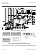
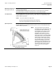
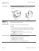
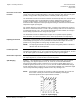
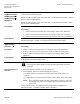
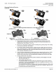
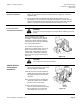
Table Of Contents

SQM5… Reversing Actuators Technical Instructions
Document No. 155-517P25
May 3, 2010
Siemens Building Technologies, Inc. Page 15
Modulation Adjustment
See Figures 10 and 12.
The blue trim potentiometers allow the adjustment of the minimum (zero) and
maximum (span) positions.
The factory setting of the MIN trim potentiometer is rotated fully counter clockwise.
The factory setting of the MAX trim potentiometer is rotated fully clockwise.
Zero Adjustment
Set the OPE/MAX/MIN slide switch to MIN. The blue MIN trim potentiometer can now
be gently adjusted to the required minimum position. Return the OPE/MAX/MIN slide
switch to OPE for operation.
NOTE: Do not set switch cam I higher than:
90° when using feedback potentiometers ASZxx.30
135° when using feedback potentiometers ASZxx.33
Span Adjustment
Set the OPE/MAX/MIN slide switch to MAX. The blue MAX trim potentiometer can now
be gently adjusted to the required maximum position. Return the OPE/MAX/MIN slide
switch to OPE for operation.
Figure 13. Switch cam and Trim
Potentiometer Setting.
NOTE: The actual minimum and maximum
modulating range is determined either by
the setting of the MIN and MAX trim
potentiometers or the setting of switch
cam III (Minimum) and switch cam I
(Maximum). The actuator can never
modulate outside of the range set by
switch cam I and III. If the MIN and MAX
trim potentiometers are set outside the
setting range of switch cams I and III,
then the switch cam settings determine
the modulating range. If a soft stop is
desired, the modulating range can be
defined by the trim potentiometers if the
MIN and MAX trim potentiometers are
set inside the setting range of switch
cams I and III. See the example in
Figure 13.