Technical Instructions Document No.
SQM5… Reversing Actuators Table Of Contents Technical Instructions Document No. 155-517P25 May 3, 2010 Application Product Numbers Table 1. Product numbers for pre-assembled UL/CSA/CE-approved actuators Table 2.
Technical Instructions Document No. 155-517P25 May 3, 2010 SQM5… Reversing Actuators Table 1. Product Numbers for Pre-assembled Actuators.
SQM5… Reversing Actuators Technical Instructions Document No. 155-517P25 May 3, 2010 Table 1. Product Numbers for Pre-assembled Actuators, Continued. 1. 2. 3. ccw cw ccw cw ccw cw cw ccw cw ccw x x x x x x x x x x x x Product Number 0-10 Vdc 50 50 50 50 50 50 50 50 50 50 0-135 W 400 400 400 400 400 400 400 400 400 400 Time 2 90°@ 60 Hzsec Input Control Signals3 4-20 mA Running Line Voltage Torque1 [lb-in] Rotation Direction Product Numbers x x x x x x x x x x x x x 110 V SQM56.
SQM5… Reversing Actuators Technical Instructions Document No. 155-517P25 May 3, 2010 2. Lift the screws and raise the cover. See Figure 3. Shaft Installation Figure 3. Figure 2. 3. Each shaft is supplied with two washers and a “C” clip. See Figure 4. Using spreading pliers, remove the “C” clip and the washers from the shaft. Figure 4. 4. Insert the “insert end” of the shaft into the “gear end” of the actuator. 5.
Technical Instructions Document No. 155-517P25 May 3, 2010 Rotational Direction Verification SQM5… Reversing Actuators Actuator model numbers that end with “R” are factory configured for clockwise (cw), minimum to maximum rotation when facing the gear end of the actuator, or counterclockwise (ccw) rotation when facing the other end of the actuator. The gear end of the actuator is the side opposite of the visual position indicator.
SQM5… Reversing Actuators Technical Instructions Document No. 155-517P25 May 3, 2010 Switch Adjustment, Continued NOTE: Shaft Adjustment The actuator shaft can be disengaged by pressing the silver shaft release button. The button is located above the grounding screw, under the hinged terminal protection cover, and to the right of the auto/manual switch. After pressing the shaft release button in and slightly upward, the shaft can be manually rotated.
Technical Instructions Document No. 155-517P25 May 3, 2010 Wiring Connections SQM5… Reversing Actuators NOTE: SQM5… actuators require a single source, single phase power supply. Wiring connections vary depending on which AGA56…. circuit board is installed. AGA56.1… circuit boards. Manual Operation See Figures 7 and 8. 1. Set the AUTO/MAN switch in the MAN position. 2. Connect ground to the screw located below the shaft release button. 3.
SQM5… Reversing Actuators Technical Instructions Document No. 155-517P25 May 3, 2010 Wiring, Continued Figure 8. AGA56.1A97 Terminal/Auto-Manual Board. Manual Operation AGA56.41/42/43… Circuit Boards. 1. Set the AUTO/MAN switch in the MAN position. See Figures 9 and 10. 2. Connect ground to the screw located below the shaft release button. 3. Connect neutral to terminal N. 4. Only terminal "L" must be powered to enable manual operation.
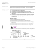
Technical Instructions Document No. 155-517P25 May 3, 2010 SQM5… Reversing Actuators Wiring, Continued Figure 9. Basic Functional Diagram of AGA56.4… Figure 10. AGA56.41/42/43… Terminal and Trim Potentiometer Boards. Page 12 Siemens Building Technologies, Inc.
SQM5… Reversing Actuators Technical Instructions Document No. 155-517P25 May 3, 2010 AGA56.9… Circuit Boards Manual Operation 1. Set the AUTO/MAN switch in the MAN position. See Figures 11 and 12. 2. Connect ground to the screw located below the shaft release button. 3. Connect neutral to terminal N. 4. Only terminal "L" must be powered to enable manual operation.
Technical Instructions Document No. 155-517P25 May 3, 2010 SQM5… Reversing Actuators Wiring, Continued Figure 11. Basic Functional Diagram of AGA56.9… Figure 12. AGA56.9… Terminal and Trim Potentiometer/Jumper Board. Page 14 Siemens Building Technologies, Inc.
SQM5… Reversing Actuators Modulation Adjustment See Figures 10 and 12. Zero Adjustment Technical Instructions Document No. 155-517P25 May 3, 2010 The blue trim potentiometers allow the adjustment of the minimum (zero) and maximum (span) positions. The factory setting of the MIN trim potentiometer is rotated fully counter clockwise. The factory setting of the MAX trim potentiometer is rotated fully clockwise. Set the OPE/MAX/MIN slide switch to MIN.
Technical Instructions Document No. 155-517P25 May 3, 2010 Cover Installation SQM5… Reversing Actuators 1. Lift the two screws on the cover corners and slide the cover end into the grooves at the gear end of the actuator. See Figure 14. 2. Press the cover into place and then press the screws inward and tighten. See Figure 15. Figure 14. Figure 15. Features of SQM5x.xxxxxZx Actuators SQM5xx.xxxxxZx actuators contain the AGA56.9A… multi function circuit board.
SQM5… Reversing Actuators Electronic Linearization Function Technical Instructions Document No. 155-517P25 May 3, 2010 Butterfly valves have non-linear flow characteristics. Near the fully closed position, a small change in the valve’s position will produce a very large change in flow. Near the fully open position, a large position change will produce a relatively small change in flow.
Technical Instructions Document No. 155-517P25 May 3, 2010 Features of SQM5x.xxxxxGx, SQM5x.xxxxxHx, SQM5x.xxxxxKx Actuators SQM5… Reversing Actuators SQM5x.xxxxxGx actuators contain the AGA56.41A… circuit board with terminals Y- and Y+ for 4 to 20 mA modulating input. SQM5x.xxxxxHx actuators contain the AGA56.42A… circuit board with terminals Y, M and U for 0 to 135 Ω modulating input. SQM5x.xxxxxKx actuators contain the AGA56.43A… circuit board with terminals Y and M for 0 to 10 Vdc modulating input.
SQM5… Reversing Actuators Reversing Rotational Direction, Continued Technical Instructions Document No. 155-517P25 May 3, 2010 8. Firmly tighten the black potentiometer cam attachment screw while manually holding the potentiometer position indication pointer in alignment. Check the alignment again. 9. Re-install the white actuator-indicating dial by gently pressing it onto the potentiometer cam attachment screw.
Technical Instructions Document No. 155-517P25 May 3, 2010 AGA56.41/42/43 Circuit Board Installation, Continued SQM5… Reversing Actuators Re-install the actuator motor capacitor. See Figure 20. Gently guide the terminal section into the support slots and slide the terminal board downward until both supports snap into place.
SQM5… Reversing Actuators AGA56.41/42/43 Circuit Board Installation, Continued Technical Instructions Document No. 155-517P25 May 3, 2010 Make the following connections to the actuator: See Figure 22. a. Connect the wire, marked “1” from the circuit board to switch I, terminal 1. b. Connect the wire, marked “2” from the circuit board to switch II, terminal 2. c. Connect the wire, marked “3” from the circuit board to switch III, terminal 3. d.
Technical Instructions Document No. 155-517P25 May 3, 2010 AGA56.9A… Circuit Board Installation, Continued SQM5… Reversing Actuators 4. Guide the base circuit board from the switch housing side of the actuator into the bottom of the circuit board mounting bracket. See Figure 23. 5. Re-install the actuator motor capacitor. See Figure 24. 6. Gently guide the terminal board into the support slots and slide the terminal board downward until both supports snap into place. See Figure 25. 7.
SQM5… Reversing Actuators AGA56.9A… Circuit Board Installation, Continued Technical Instructions Document No. 155-517P25 May 3, 2010 8. Gently guide the L-shaped circuit board containing the three blue trim potentiometers into the vertical support slots located on the cam drum side of the actuator. See Figure 27. 9. Slide the circuit board downward until both supports snap into place. Install the ASZ… potentiometer. (See Potentiometer Removal/Installation Instructions.) 10.
Technical Instructions Document No. 155-517P25 May 3, 2010 Potentiometer Removal SQM5… Reversing Actuators Remove the white plastic actuator position-indicating dial by gently pulling while rotating in the clockwise direction. See Figure 6. Disconnect the blue, black and brown wire from the potentiometer terminal block. See Figure 17. Remove the silver potentiometer alignment screw. Loosen the black potentiometer cam attachment screw approximately one turn.
SQM5… Reversing Actuators Specifications SQM5... Reversing Actuator Technical Instructions Document No. 155-517P25 May 3, 2010 SQM5... Reversing actuator Agency approvals Operating voltage Operating frequency Power consumption Type of motor Duty cycle Torque Maximum shaft torque AGA58.1 AGA58.2 AGA58.3 AGA58.4 AGA58.7 Timings Rotational range of operation SQM5x.xxxxxA models SQM5x.xxxxxx3 models SQM5x.xxxxxx4 models SQMSx.
Technical Instructions Document No. 155-517P25 May 3, 2010 Specifications SQM5… Reversing Actuators Conduit connection SQM5... Reversing Actuator, Continued Gears and bearings Mounting Adaptation to other actuator brands Circuit Boards AGA56.1A97 AGA56.1A97 Switch circuit board Operating voltage Operating frequency Auto/manual switch Manual toggle switch Ambient operating temperature Shipping temperature Weight AGA56.41A… Electronic circuit boards Operating voltage AGA56.
SQM5… Reversing Actuators Technical Instructions Document No. 155-517P25 May 3, 2010 Specifications, continued AGA56.43A… AGA56.43A… Electronic circuit boards Input signal Impedance Voltage input AGA56.9A AGA56.9A… Multi function electronic circuit boards Operating voltage Operating frequency Input signals Same specifications as AGA56.41A except: 0 to 10 Vdc ≥100K Ω Single potentiometer ASZ...
Technical Instructions Document No. 155-517P25 May 3, 2010 Dimensions SQM5… Reversing Actuators The first dimension given is measured in inches. Millimeters are shown in parentheses. Figure 28. SQM5x.xxxRxx Dimensions. Page 30 Siemens Building Technologies, Inc.
SQM5… Reversing Actuators Technical Instructions Document No. 155-517P25 May 3, 2010 Dimensions, Continued Figure 29. Mounting Bracket AGA57.3. Figure 30. AGA57.4 Mounting Bracket. Siemens Building Technologies, Inc.