
User Guide


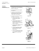
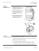
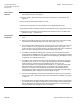
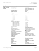
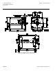
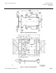
Table Of Contents

SQM5… Reversing Actuators Technical Instructions
Document No. 155-517P25
May 3, 2010
Siemens Building Technologies, Inc. Page 25
AGA56.9A…
Circuit Board
Installation, Continued
8. Gently guide the L-shaped circuit board
containing the three blue trim
potentiometers into the vertical support
slots located on the cam drum side of
the actuator. See Figure 27.
9. Slide the circuit board downward until
both supports snap into place. Install
the ASZ… potentiometer. (See
Potentiometer Removal/Installation
Instructions.)
10. Connect the bundled blue, black and
brown potentiometer wires to the
terminal block located on the ASZ…
potentiometer circuit board.
Figure 26.
Figure 27.
AGA56.1A97
Circuit Board Installation
1. Install the AGA56.1A97 circuit board into the two slotted circuit board supports located
on the switch housing side of the actuator.
2. Gently guide the AGA56.1A97 circuit board into the support slots and slide the board
downward until both supports snap into place.
3. Make the following connections to the actuator:
a. Connect the wire, marked “1” from the circuit board to switch I, terminal 1.
b. Connect the wire, marked “2” from the circuit board to switch II, terminal 2.
c. Connect the wire, marked “13” from the circuit board to switch III, terminal 13.