
User Guide


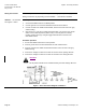
Table Of Contents

Technical Instructions SQM5… Reversing Actuators
Document No. 155-517P25
May 3, 2010
Page 8 Siemens Building Technologies, Inc.
Rotational Direction
Verification
Actuator model numbers that end with “R” are factory configured for clockwise (cw),
minimum to maximum rotation when facing the gear end of the actuator, or
counterclockwise (ccw) rotation when facing the other end of the actuator. The gear end
of the actuator is the side opposite of the visual position indicator.
To field reverse the direction of rotation, see Service Guide, “Reversing Rotational
Direction”.
Actuator Mounting
SQM5… actuators can be mounted in any orientation using the four holes located on the
bottom corners of the actuator base. Optional base mounting brackets are available.
See Table 2.
SQM5… actuators can also be face mounted using self tapping screws in combination
with the various holes on the face of the actuator gear end.
Figure 6. Component Identification on the Cam Drum Side of the SQM5… Actuator.
Switch Adjustment
See Figure 6.
All SQM5…actuators are factory wired with Switch I (maximum), Switch II (fully closed
“economy position”) and Switch III (minimum). The individual switch cams I, II, and III
are factory set to 90°, 0° and 10° respectively.
NOTE: The single switch cam pointers are used together with the black scales when
configured for counterclockwise (ccw) operation.
The double switch cam pointers are used together with the red scales when
configured for clockwise (cw) operation.
The individual switch cams can be adjusted by hand or with the use of the tool
attached to the outside of the hinged switch terminal protection lid.