
User Guide
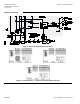

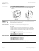
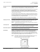
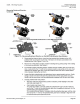
Table Of Contents

SQM5… Reversing Actuators Technical Instructions
Document No. 155-517P25
May 3, 2010
Siemens Building Technologies, Inc. Page 17
Electronic Linearization
Function
Butterfly valves have non-linear flow characteristics. Near the fully closed position, a small
change in the valve’s position will produce a very large change in flow. Near the fully open
position, a large position change will produce a relatively small change in flow.
The linearization function is intended to minimize the initial steep flow curve characteristics
of a typical butterfly valve. The linearization function is enabled when Jumper J1 is in
position 1 (upper position). Consequently, the actuator will make smaller rotational
movements when subjected to lower input signals and larger rotational movements when
subjected to higher input signals.
For example (based on a 90° modulating range), a change in input signal from 4 to 8 mA
will cause a rotational movement of 11.25°. An equal change from 16 to 20 mA will cause
a rotational movement of 45°. Thus, with the linearization function enabled, the change in
flow is closely proportional to the change in input signal.
The linearization function is disabled when Jumper J1 is in position 2 (lower position).
When disabled, the rotational movement of the shaft is proportional to the input signal.
Input Signal Override
Line voltage to terminal P will drive the actuator to a pre-set adjustable position, overriding
all modulating input signals. Use the potentiometer marked POS to adjust the override
position to any setting within the setting range of switch cams I and III.
NOTE: The input signal override can also be used for the ignition position of burners if
different from the low fire position.
Parallel Operation
Set Jumper J2 in position 1 (upper position) to configure the actuator for parallel
operation. Input signals Y0, Y1, Y2 or Y3 are directly shunted to output signals U1, U2 and
U3. All output signals are available regardless of which input signal is applied.
Master/Slave Operation
Set J2 in position 2 (lower position) to configure the actuator for master/slave operation.
The output signals U1, U2 and U3 reflect actual shaft position.
Split Ranging
AGA56.9… circuit boards have a modulating signal shift feature which can be used for
split ranging. If no signal is present on Y0, Y1, Y2 or Y3, the actuator will modulate
through the full rotational range in response to a 12 to 20 mA signal applied at ZF. If a
maximum signal is present on Y0, Y1, Y2, or Y3, then the actuator will modulate through
the full rotational range in response to a 4 to 12 mA signal applied at ZF. (Maximum signal
can be easily achieved by bridging terminals U4 and Y0.) See Figure 16.
NOTE: It is possible to configure the actuator for split range operation 12 to 4 mA and
20 to 12 mA. Consult your authorized Siemens Building Technologies
combustion products sales representative for details.
Figure 16. Split Ranging.