
Installation Instructions

Installation Instructions
Document No. 129-801
June 19, 2015
SQV Series Electromotoric Valve
Actuators
(For use with 2-1/2 to 6-inch Pressure Independent
Control Valves)
Item Number 129-801, Rev. DA Page 1 of 7
Product Description
The SQV spring return (fail-safe) actuator requires a
24 volt power supply and a 0 to 10 Vdc or floating
control signal to control the Pressure Independent
Control series valve with 3/4-inch to 1-1/2-inch (20 to
40 mm) stroke.
Product Numbers
SQV91P30U Normally Open
SQV91P40U Normally Closed
Contents
• SQV Actuator
• Conduit Adapter
• Stroke Indicators (2)
• Anti-rotation Device
Warning/Caution Notations
WARNING:
Personal injury or loss of life
may occur if you do not follow
the procedures as specified.
CAUTION:
Equipment damage or loss of
data may occur if you do not
follow the procedures as
specified.
Troubleshooting
• Check the wiring for the proper connections.
• If actuator becomes inoperable, replace the
unit.
Required Tools
• 6 mm hex key
• 3/16” flat-blade screwdriver or T15 Torx
driver (to remove wiring compartment cover)
• Small, flat-blade screwdriver (for wiring
terminal block)
Expected Installation Time
20 to 30 minutes
Prerequisites
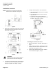
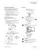
Figure 1. Acceptable Mounting Positions.
NOTE: This device complies with part 15 of the
FCC Rules. Operation is subject to the
following two conditions: (1) This device may
not cause harmful interference, and (2) this
device must accept any interference
received, including interference that may
cause undesired operation.
NOTE: This equipment is intended to be supplied by
a Class 2 power source. All control signals
and output are Class 2 AC/DC.
Allowed wire size: 16 to 20 AWG
Installation
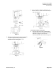
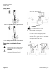
1. Using a 6 mm hex wrench, loosen the two hex
head cap screws on the bonnet connection. See
Figure 2.
Figure 2. Hex Head Cap Screws.