Electromotoric actuator SSA118.09HKN With KNX communication for radiator valves, PICV and small valves ● ● ● ● ● ● ● A6V11858280_en--_b 2021-08-06 Support of KNX S-Mode (integration with ETS) Support of KNX PL-Link (integration with Desigo™ Room Automation) Direct mounting with coupling nut, no tools required Position and actuator motion indication (LED) Positioning force 100 N Parallel operation of multiple actuators possible Integral cable length 1.
Product and application description The valve actuator SSA118.09HKN is suitable for installation on radiator or zone valves. It supports KNX PL-Link and S-Mode. It receives the setting commands via the KNX bus line from a room temperature controller (RTC). The valve actuator with integrated bus coupling unit is connected via a bus connecting block to the KNX bus line. The power supply results from the bus voltage. The valve adjustment works in proportion to an electromotive drive.
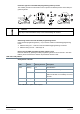
HMI (Human-Machine Interface) Overview 1 Protective cover for manual operation. Use a screwdriver to open before manually adjusting the actuator stem position. 2 Enable/disable button of manual operation 3 Hand adjustment with hex key for manual operation 4 KNX programming button 5 Stem position LED indicator 6 KNX programming LED Enable/disable button of manual operation Activity Button operation Confirmation Enter/exit local override mode Press button > 3 s.
Protection against unintended KNX programming button pressure The actuator provides a mechanical function to prevent accidental pressure of the KNX programming button. NOTICE Fully align A and B illustrated in Step 5 when reassembling the actuator. Addressing and bus test with the KNX programming button Press the KNX programming button (< 2 s) to set the actuator to addressing/programming mode: ● KNX bus wiring OK → LED turns red until addressing/programming is finished.
KNX programming LED Color Pattern Flashing interval Description Green Constant - Connection test successful Yellow Flashing 0.1 s Factory reset in progress 1.75 s After connection test: wait Constant - Device is in programming/addressing mode Flashing 2s Internal error: Power reset necessary 1s After connection test: Connection test failed Red Type summary Type Stock number SSA118.09HKN S55180-A111 Operating voltage Running speed Running time Control sig2.
Equipment combinations Valves Type reference Valve type Kvs [m3/h] V̇ [I/h] PN class Data sheet VDN.., VEN.., VUN.. Radiator valves 0.09…1.41 - PN 10 VPD.., VPE.. MCV radiator valves - 25…483* N2185 VD1..CLC Small valves 0.25…2.60 - N2103 VPP46.., VPI46.. PICV valves DN10..DN32 - 30…4001 PN 25 N2105, N2106 N4855 Kvs: Nominal flow rate of cold water (5…30 °C) through the fully open valve (H100) by a differential pressure of 100 kPa (1 bar). Radiator valves (M30 × 1.
Product documentation Topic Title Document ID: Mounting and installation Mounting instructions1) A6V11858274 Standards and directives CE declarations A5W00106106A RCM conformity A5W00106107A Environmental compatibility Environmental declarations A5W00109220A KNX PL-Link and S-Mode programming Application program description A6V12066162 1) Mounting instructions enclosed with product packaging. Related documents such as environmental declarations, CE declarations etc.
● ● If re-mounting to another valve is necessary, dismantle the actuator from the current valve by rotating the actuator stem anti-clockwise. See Mounting instructions enclosed with the product package for graphical instructions. Orientation Installation A [mm] B [mm] C [mm] 4.35 4.2 70 Crimp ferrule on stripped wire of connecting cable. ● Observe all admissible temperatures (see “Technical data [▶ 12]”). ● Operate the actuator only with alternating current (see “Technical data [▶ 12]”).
NOTICE Commission the actuator only with a valve mounted correctly in place! Self-calibration The actuator self-calibrates (fully retracted ➙ fully extended ➙ setpoint) after initial connection of bus voltage, after every download of the application, and after bus voltage recovery. During calibration, the valve is measured and the positions for “valve open” and “valve closed” are stored.
3. Adjust the actuator stem position by rotating the manual operation button clockwise or anti-clockwise. The actuator stem moves down if you rotate clockwise; it moves up if you rotate anticlockwise. The manually set position is retained. 4. If you want to exit the manual operation mode, press and hold down the enable/disable button of manual operation for at least three seconds. The actuator self-calibrates automatically. A control signal sent from the controller takes effect. 5.
Disposal The device is considered an electronic device for disposal in accordance with European guidelines and may not be disposed of as domestic waste. ● Dispose of the device through channels provided for this purpose. ● Comply with all local and currently applicable laws and regulations. Open Source Software (OSS) Software license overview These devices use Open Source Software (OSS).
Technical data Power supply KNX bus voltage DC 24 V (DC 21…30 V) KNX bus current Running Max. 15 mA Holding 5 mA KNX power loss (internal consumption) Approx. 0.36 W Signal input Control signal Via KNX bus Parallel operation (number of actuators)1) 64 1) Limitation only in PL-Link mode. Provided that the controller output is sufficient. Operating data Positioning speed 20 s/mm ± 25 % Positioning force 100 N Stroke 1.2…6.5 mm Permissible temperature of medium in the connected valve 1...
Protection settings Pollution degree rating as per EN 60730-1 2 Overvoltage category as per EN 60730-1 III Housing protection degree IP 54 Protection class as per EN 60730 II Electrical safety, bus Safe extra low voltage SELV DC 29 V Electrical safety, device complies with EN 60730-1 EMC requirements, device complies with EN 50491-5-1, EN 50491-5-2, EN 50491-5-3 Reliability Failure rate (at 20 ℃) 1141 fit General ambient conditions Operation EN 60721-3-3 Transport EN 60721-3-2 Storage EN 6
NOTICE DI1 and DI2 can be connected to any Open/Close contact (window contact, condensation contact, presence detector, etc.). We recommend connecting DI1 to a window contact and DI2 to a presence detector or condensation contact.
Support ● ● ● Hand over the operating instructions and all other technical product information to the client. Return faulty devices with a return delivery note to the local Siemens office. For technical questions, contact: – +49 (911) 895-7222 – +49 (911) 895-7223 – support.automation@siemens.com – http://www.siemens.com/supportrequest Technical Support: http://www.siemens.com/supportrequest FAQ FAQ: https://support.industry.siemens.
Issued by Beijing Siemens Cerberus Electronics Ltd. Smart Infrastructure No.1, Fengzhi East Road, Xibeiwang Haidian District, 100094 BEIJING, China +86 10 64768806 www.siemens.com/buildingtechnologies Document ID A6V11858280_en--_b Edition 2021-08-06 © Beijing Siemens Cerberus Electronics Ltd., 2021 Technical specifications and availability subject to change without notice.