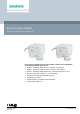
Electromotoric actuator SSA131.00, SSA331.00, SSA161.05 For pressure independent combi valves (PICV), radiator valves, MiniCombi valves (MCV) and small globe valves ● ● ● ● ● ● ● ● A6V11858276_en--_e 2021-08-06 SSA131.. Operating voltage AC 24 V, 3-position control signal SSA331.. Operating voltage AC 230 V, 3-position control signal SSA161.. Operating voltage AC/DC 24 V, positioning signal DC 0...
Use ● ● ● ● ● ● ● For radiator valves, VDN.., VEN.., VUN.. For Siemens PICV (pressure independent combi valves) VPP46.. and VPI46.. For MiniCombi valves VPD.., VPE.. For small valves VD1..CLC For radiator valves (M30 × 1.5) from other manufacturers without adapter Typically in radiator, chilled ceiling, VAV and fan coil unit applications. Max. 24 units of SSA131.00, 6 units of SSA331.00 or 10 units of SSA161.05 are able to operate in parallel, provided the controller output suffices.
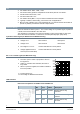
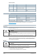
LED colors and patterns for SSA161.05 LED color Pattern Flashing interval Green Flashing 0.1 s Self-calibration 0.5 s Red Description Actuator stem is moving. Constant - Actuator stem reaches a set position. The LED turns off after it is constantly on for five seconds. Constant - Error* * Hint: calibration or power reset required. Type summary Type Stock number Operating voltage Running speed at 50 Hz Running time Control signal 2.5 mm Cable length SSA131.
Equipment combinations Valves Type reference Valve type Kvs [m3/h] V̇ [I/h] PN class Data sheet VDN.., VEN.., VUN.. Radiator valves 0.09…1.41 - PN 10 VPD.., VPE.. MCV radiator valves - 25…483* N2185 VD1..CLC Small valves 0.25…2.60 - N2103 VPP46.., VPI46.. PICV valves DN10..DN32 - 30…4001 PN 25 N2105, N2106 N4855 Kvs: Nominal flow rate of cold water (5…30 °C) through the fully open valve (H100) by a differential pressure of 100 kPa (1 bar) Radiator valves (M30 × 1.
Room thermostats Type SSA131.00 RDG.. RDG405KN SSA331.00 SSA161.05 RDG100KN, RDG100, RDG100T RDG160KN, RDG160T, RDG405KN RDF.. - RDF800KN, RDF800KN/NF, RDF302, RDF600, RDF600T, RDF600KN - RDU.. - - RDU340 RCU.. - - RCU50..
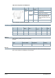
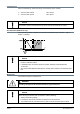
● See Mounting instructions enclosed with the product package for graphical instructions. Orientation Installation A [mm] B [mm] C [mm] SSA131.00 4.5 4.2 50 SSA331.00 5.9 6.0 50 SSA161.05 4.5 4.2 50 Crimp ferrule on stripped wire of connecting cable. ● Observe all admissible temperatures (see “Technical data [▶ 9]”). ● Operate the actuator only with alternating current for SSA131.00 and SSA331.00 (see “Technical data [▶ 9]”). ● ● ● Do not twist the cable.
Commissioning When commissioning, check both wiring and functioning of the actuator. ● Actuator stem extends Valve closes ● Actuator stem retracts Valve opens NOTICE The actuator must be commissioned only with a correctly mounted valve in place! Self-calibration (SSA161.05 only) When operating voltage is applied, the actuator self-calibrates (fully retracted ➙ fully extended ➙ setpoint). NOTICE ● Correct calibration is only possible with valve stroke > 1.2 mm. Valve stroke < 1.
Repair The actuators cannot be repaired; the complete unit must be replaced. Disposal The device is considered an electronic device for disposal in accordance with European guidelines and may not be disposed of as domestic waste. ● Dispose of the device through channels provided for this purpose. ● Comply with all local and currently applicable laws and regulations. Warranty Technical data on specific applications are valid only together with Siemens products listed under "Equipment combinations".
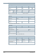
Technical data Power supply SSA131.00 SSA331.00 SSA161.05 Operating voltage AC 24 V AC 230 V AC 24 V DC 24 V Tolerance ± 20 % ± 15 % ± 15 % ± 20 % Frequency Power consumption 50/60 Hz Running 0.8 VA 7 VA 2.5 VA Holding 0.2 VA 0.2 VA 2 VA Primary fuse or breaker rating External, 2 A quick blow Signal input SSA131.00 SSA331.00 SSA161.05 Control signal 3-position DC 0...10 V Input impedance for DC 0...10 V - 100 kOhm Parallel operation (number of actuators)1) Max. 24 1) Max.
Mounting Fixing on valve Plastic coupling nut M30 × 1.5 Orientation 360° Standards SSA131.00 SSA331.00 SSA161.
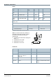
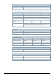
Diagrams Connection terminals SSA131.00 Y1 = Control signal OPEN (AC 24 V) Y2 = Control signal CLOSE (AC 24 V) G = System potential AC 24 V SSA331.00 Y1 = Control signal OPEN (AC 230 V) Y2 = Control signal CLOSE (AC 230 V) N = Neutral SSA161.05 G = System potential AC 24 V (+ DC 24 V) Y = Control signal DC 0...10 V G0 = System neutral (- DC 24 V) Connection diagrams SSA131.
SSA331.00 N = Controller Y = Actuator L = System potential AC 230 V N = System neutral Y1, Y2 = Control signal OPEN, CLOSE Q1, Q2 = Controller contacts SSA161.
Revision numbers Type Valid from rev. no. SSA131.00 ..A SSA331.00 ..A SSA161.05 ..
Issued by Beijing Siemens Cerberus Electronics Ltd. Smart Infrastructure No.1, Fengzhi East Road, Xibeiwang Haidian District, 100094 BEIJING, China +86 10 64768806 www.siemens.com/buildingtechnologies Document ID A6V11858276_en--_e Edition 2021-08-06 © Beijing Siemens Cerberus Electronics Ltd., 2021 Technical specifications and availability subject to change without notice.