
Data Sheet for Product


Technical Bulletin TB254 599 Series Zone Valve and Actuator Assembly Selection
Document Number 155-291
February 9, 2018
Page 2 Siemens Industry, Inc.
Selection Examples
In an ANSI 125 piping system, a two-way, normally closed, female-by-female, NPT
threaded valve delivers 6 gpm (0.52 m
3
/hr) chilled water with no more than 6-psi
(41.4 kPa) pressure drop across the fully open valve.
The actuator shall receive 120 Vac power; accept a two-position control signal, and
provide normally closed operation. The actuator closes off tightly against a pump head
pressure of 14.5 psi (100 kPa, 1 bar).
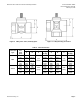
Specifications
Valve Sizing
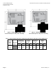
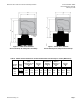
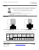
See Figure 1, the Water Capacity Graph, to select the valve size as follows:
1. Locate the required flow rate by finding gpm (m
3
/hr) on the vertical axis.
2. Follow across the horizontal axis and find the psi (kPa) maximum allowable
pressure drop across the open valve.
3. Select the valve line size that will ensure proper flow.
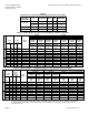
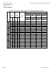
Assembly
(Product Number)
Selection: An Example
Use Table 4 to select a valve and actuator assembly as follows:
1. Read the table from left to right and select a NPT connection. Select a 0.50-inch
(15 mm), 2.5 Cv (2.0 Kvs) valve. The valve body part number is
599-00211.
2. Read across the top of the table and select a normally closed, 120 Vac actuator
prefix code. The prefix number is 240.
3. Read down the SFA11U actuator column and across the 0.50-inch (15 mm) valve
body row to select 240-00211. The column/row intersection determines the
appropriate valve and actuator assembly.
Alternatively, the valve and actuator can be ordered separately.