
Data Sheet for Product
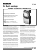


Air Duct Housings
• Series IL, and Series 3 Ionization or
Photoelectric Detectors
• Optional Relays for Supplementary
Equipment Operation
• Optional Control Module for Self-contained
Operation (Series 3 Detectors Only)
• Alarm LED Visible from Front
• Clear Housing Cover for Quick
Identification of Detector Type
• Listed, ULC Listed, NYMEA, FM,
CSFM and City of Chicago Approved
6124
CATALOG NUMBER
Introduction
The Siemens Building Technologies, Inc., Fire Safety
Division air duct detector housings are designed to be used
with Fire Safety Series IL, ID-60 and Series 3 ionization or
photoelectric detectors. Designed for installation directly to
heating, ventilating and air conditioning duct systems, they
comply with National Fire Protection Association Standard
No. 90A. When equipped with ionization or photoelectric
detectors, these units will signal the presence of hazardous
quantities of products of combustion or smoke being carried
through the duct system. Air duct detectors are not intended
to be substituted for open area detection.
Air duct housings can be equipped with optional relays.
These relays are utilized to operate any supplementary
equipment when smoke or particles of combustion are
detected.
Note: On most control equipment, including System 3,
only one detector per zone is permitted when the detec-
tor operated relay function is critical. The connection of a
remote lamp or a remote relay per detector is allowed,
but not both.
The XL3 control panel assures operation of all detector
operated relays, therefore up to 30 detectors per circuit
having relays for critical functions may be used. For the
MXL control panel, up to 60 detectors per circuit having
relays may be used. The connection of a remote lamp or
a remote relay is allowed for each detector but not both.
Air duct housings (see Ordering Information) are Under-
writers Laboratories, Inc. listed.
Description
The Fire Safety air duct housing is uniquely designed to
use the highly sensitive yet stable Series IL, ID-60 and
Series 3 detectors.
The sensitivity of Series 3 detectors can be checked in
place under actual dynamic air flow conditions using a Fire
Safety sensitivity test module. The sensitivity of Series IL
detectors can be checked in place under actual dynamic
conditions at the XL3 control panel, MXL control panel or
IXL respectively or may be printed by command on the
optional printer.
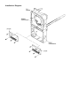
The detector unit employs a cross-sectional sampling
principle of operation. Inlet sampling tubes are available in
four lengths (see table on reverse side). Outlet sampling
tubes are one common length. A continuous cross-
sectional sample of air moving through the duct is taken.
This averages the effects of laminar flow, stratification or
skin effect phenomena occurring in the duct that could
prevent combustion products or smoke (especially in
large ducts) from reaching a spot type detector.
In addition, the unique design of the Fire Safety sampling
chamber insures uniform sensitivity in air velocities,
ranging from a low of 300 feet per minute to as high as
4000 feet per minute.