
Technical data


Table Of Contents
- Title
- Preface
- Contents
- 1 Organization Blocks
- 1.1 Overview of the Organization Blocks (OBs)
- 1.2 Program Cycle Organization Block (OB1)
- 1.3 Time-of-Day Interrupt Organization Blocks ( OB10 to OB17)
- 1.4 Time-Delay Interrupt Organization Blocks ( OB20 to OB23)
- 1.5 Cyclic Interrupt Organization Blocks (OB30 to OB38)
- 1.6 Hardware Interrupt Organization Blocks ( OB40 to OB47)
- 1.7 Status Interrupt OB (OB 55)
- 1.8 Update Interrupt OB (OB 56)
- 1.9 Manufacturer Specific Interrupt OB (OB57)
- 1.10 Multicomputing Interrupt Organization Block (OB60)
- 1.11 Synchronous Cycle Interrupt OBs (OB 61 to OB 64)
- 1.12 Technology Synchronization Interrupt OB (OB 65)
- 1.13 I/O Redundancy Error OB (OB70)
- 1.14 CPU Redundancy Error OB (OB72)
- 1.15 Communication Redundancy Error OB (OB73)
- 1.16 Time Error Organization Block (OB80)
- 1.17 Power Supply Error Organization Block (OB81)
- 1.18 Diagnostic Interrupt Organization Block (OB82)
- 1.19 Insert / Remove Module Interrupt Organization Block ( OB83)
- 1.20 CPU Hardware Fault Organization Block (OB84)
- 1.21 Priority Class Error Organization Block (OB85)
- 1.22 Rack Failure Organization Block (OB86)
- 1.23 Communication Error Organization Block (OB87)
- 1.24 Processing Interrupt OB (OB 88)
- 1.25 Background Organization Block (OB90)
- 1.26 Startup Organization Blocks (OB100, OB101 and OB102)
- 1.27 Programming Error Organization Block (OB121)
- 1.28 I/O Access Error Organization Block (OB122)
- 2 Common Parameters for SFCs
- 3 Copy and Block Functions
- 3.1 Copying Memory Area with SFC 20 "BLKMOV"
- 3.2 Uninterruptible Copying of Variables with SFC 81 " UBLKMOV"
- 3.3 Initializing a Memory Area with SFC 21 "FILL"
- 3.4 Creating a Data Block with SFC 22 "CREAT_DB"
- 3.5 Deleting a Data Block with SFC 23 "DEL_DB"
- 3.6 Testing a Data Block with SFC 24 "TEST_DB"
- 3.7 Compressing the User Memory with SFC 25 " COMPRESS"
- 3.8 Transferring a Substitute Value to Accumulator 1 with SFC 44 " REPL_ VAL"
- 3.9 Generating Data Blocks in Load Memory with SFC 82 " CREA_ DBL"
- 3.10 Reading from a Data Block In Load Memory with SFC 83 " READ_ DBL"
- 3.11 Writing a Data Block in Load Memory with SFC 84 " WRIT_ DBL"
- 3.12 Creating a Data Block with SFC 85 "CREA_DB"
- 4 SFCs for Controlling Program Execution
- 5 SFCs for Handling the System Clock
- 6 SFCs for Handling Run-Time Meters
- 7 SFCs/SFBs for Transferring Data Records
- 7.1 Writing and Reading Data Records
- 7.2 Reading Defined Parameters with SFC 54 " RD_ DPARM"
- 7.3 Reading Predefined Parameters with SFC 102 " RD_ DPARA"
- 7.4 Writing Dynamic Parameters with SFC 55 "WR_PARM"
- 7.5 Writing Default Parameters with SFC 56 "WR_DPARM"
- 7.6 Assigning Parameters to a Module with SFC 57 " PARM_ MOD"
- 7.7 Writing a Data Record with SFC 58 "WR_REC"
- 7.8 Reading a Data Record with SFC 59 "RD_REC"
- 7.9 Further Error Information for SFCs 55 to 59
- 7.10 Reading Predefined Parameters with SFB 81 " RD_ DPAR"
- 8 DPV1 SFBs According to PNO AK 1131
- 9 SFCs for Handling Time-of-Day Interrupts
- 9.1 Handling Time-of-Day Interrupts
- 9.2 Characteristics of SFCs 28 to 31
- 9.3 Setting a Time-of-Day Interrupt with SFC 28 " SET_ TINT"
- 9.4 Canceling a Time-of-Day Interrupt with SFC 29 " CAN_ TINT"
- 9.5 Activating a Time-of-Day Interrupt with SFC 30 " ACT_ TINT"
- 9.6 Querying a Time-of-Day Interrupt with SFC 31 " QRY_ TINT"
- 10 SFCs for Handling Time-Delay Interrupts
- 11 SFCs for Handling Synchronous Errors
- 12 SFCs for Handling Interrupts and Asynchronous Errors
- 12.1 Delaying and Disabling Interrupt and Asynchronous Errors
- 12.2 Disabling the Processing of New Interrupts and Asynchronous Errors with SFC 39 " DIS_ IRT"
- 12.3 Enabling the Processing of New Interrupts and Asynchronous Errors with SFC 40 " EN_ IRT"
- 12.4 Delaying the Processing of Higher Priority Interrupts and Asynchronous Errors with SFC 41 " DIS_ AIRT"
- 12.5 Enabling the Processing of Higher Priority Interrupts and Asynchronous Errors with SFC 42 " EN_ AIRT"
- 13 SFCs for Diagnostics
- 13.1 System Diagnostics
- 13.2 Reading OB Start Information with SFC 6 "RD_SINFO"
- 13.3 Reading a System Status List or Partial List with SFC 51 " RDSYSST"
- 13.4 Writing a User-Defined Diagnostic Event to the Diagnostic Buffer with SFC 52 " WR_ USMSG"
- 13.5 Determining the OB Program Runtime with SFC 78 " OB_ RT"
- 13.6 Diagnosis of the Current Connection Status with SFC 87 " C_ DIAG"
- 13.7 Identifying the Bus Topology of a DP Master System with SFC 103 " DP_ TOPOL"
- 14 SFCs and SFBs for Updating the Process Image and Processing Bit Fields
- 14.1 Updating the Process Image Input Table with SFC 26 " UPDAT_ PI"
- 14.2 Updating the Process Image Output Table with SFC 27 " UPDAT_ PO"
- 14.3 Updating the Process Image Partition Input Table in a Synchronous Cycle with SFC 126 " SYNC_ PI"
- 14.4 Updating the Process Image Partition in a Synchronous Cycle with SFC 127 " SYNC_PO"
- 14.5 Setting a Bit Field in the I/O Area with SFC 79 "SET"
- 14.6 Resetting a Bit Field in the I/O Area with SFC 80 " RSET"
- 14.7 Implementing a Sequencer with SFB 32 "DRUM"
- 15 System Functions for Addressing Modules
- 15.1 Querying the Logical Base Address of a Module with SFC 5 " GADR_ LGC"
- 15.2 Querying the Module Slot Belonging to a Logical Address with SFC 49 " LGC_ GADR"
- 15.3 Querying all Logical Addresses of a Module with
- 15.4 Determining the Slot Belonging to a Logical Address with SFC 71 " LOG_ GEO"
- 15.5 Determining the Slot Belonging to a Logical Address
- 16 SFCs for Distributed I/Os or PROFINET IO
- 16.1 Triggering a Hardware Interrupt on the DP Master with SFC 7 " DP_ PRAL"
- 16.2 Synchronizing Groups of DP Slaves with SFC 11 " DPSYC_ FR"
- 16.3 Deactivating and Activating DP Slaves/PROFINET IO Devices with SFC 12 " D_ ACT_ DP"
- 16.4 Reading Diagnostic Data of a DP Slave with SFC 13 " DPNRM_ DG" ( Slave Diagnostics)
- 16.5 Reading Consistent Data of a DP Standard Slave// PROFINET IO Device with SFC 14 " DPRD_DAT"
- 16.6 Writing Consistent Data to a DP Standard Slave/ PROFINET IO Device with SFC 15 " DPWR_DAT"
- 17 PROFInet
- 17.1 Background Information on SFCs 112, 113 and 114
- 17.2 Updating the Inputs of the User Program Interface for the PROFInet Component with SFC 112 " PN_ IN"
- 17.3 Updating the Outputs of the PROFInet Interface for the PROFInet Component with SFC 113 " PN_ OUT"
- 17.4 Updating DP Interconnections with SFC 114 "PN_DP"
- 18 FBs for Cyclical Access to User Data according to the PNO
- 18.1 Introduction to the FBs for Cyclical Access to User Data according to the PNO
- 18.2 Read All Inputs of a DP Standard Slave/PROFINET IO Device with FB 20 " GETIO"
- 18.3 Write All Outputs of a DP Standard Slave/PROFINET IO Device with FB 21 " SETIO"
- 18.4 Read a Part of the Inputs of a DP Standard Slave/ PROFINET IO Device with FB 22 " GETIO_PART"
- 18.5 Write a Part of the Outputs of a DP Standard Slave/ PROFINET IO Device with FB 23 " SETIO_PART"
- System Software for S7- 300/ 400 System and Standard Functions Volume 1/ 2
- Contents
- 19 SFCs for Global Data Communication
- 20 Overview over the S7 Communication and the S7 Basic Communication
- 21 S7 Communication
- 21.1 Common Parameters of the SFBs/FBs and SFCs/FCs for S7 Communication
- 21.2 Startup Routine of SFBs for Configured S7 Connections
- 21.3 How SFBs React to Problems
- 21.4 Uncoordinated Sending of Data with SFB 8/FB 8 " USEND"
- 21.5 Uncoordinated Receiving of Data with SFB/FB 9 " URCV"
- 21.6 Sending Segmented Data with SFB/FB 12 "BSEND"
- 21.7 Receiving Segmented Data with SFB/FB 13 "BRCV"
- 21.8 Writing Data to a Remote CPU with SFB/FB 15 "PUT"
- 21.9 Read Data from a Remote CPU with SFB/FB 14 "GET"
- 21.10 Sending Data to a Printer with SFB 16 "PRINT"
- 21.11 Initiating a Warm or Cold Restart on a Remote Device with SFB 19 " START"
- 21.12 Changing a Remote Device to the STOP State with SFB 20 " STOP"
- 21.13 Initiating a Hot Restart on a Remote Device with SFB 21 " RESUME"
- 21.14 Querying the Status of a Remote Partner with SFB 22 " STATUS"
- 21.15 Receiving the Status Change of a Remote Device with SFB 23 " USTATUS"
- 21.16 Querying the Status of the Connection Belonging to an SFB Instance with SFC 62 " CONTROL"
- 21.17 Querying the Connection Status with FC 62 " C_ CNTRL"
- 21.18 Work Memory Requirements of the S7 Communication SFBs/ FBs
- 22 Communication SFCs for Non-Configured S7 Connections
- 22.1 Common Parameters of the Communication SFCs
- 22.2 Error Information of the Communication SFCs for Non- Configured S7 Connections
- 22.3 Sending Data to a Communication Partner outside the Local S7 Station with SFC 65 " X_ SEND"
- 22.4 Receiving Data from a Communication Partner outside the Local S7 Station with SFC 66 " X_ RCV"
- 22.5 Writing Data to a Communication Partner outside the Local S7 Station with SFC 68 " X_ PUT"
- 22.6 Reading Data from a Communication Partner outside the Local S7 Station with SFC 67 " X_ GET"
- 22.7 Aborting an Existing Connection to a Communication Partner outside the Local S7 Station with SFC 69 " X_ ABORT"
- 22.8 Writing Data to a Communication Partner within the Local S7 Station with SFC 73 "I_PUT"
- 22.9 Reading Data from a Communication Partner within the Local S7 Station with SFC 72 "I_GET"
- 22.10 Aborting an Existing Connection to a Communication Partner within the Local S7 Station with SFC 74 " I_ ABORT"
- 23 Open Communication via Industrial Ethernet
- 23.1 Overview
- 23.2 Function of FBs for Open Communication via Industrial Ethernet
- 23.3 Assigning Parameters for Communications Connections with TCP native and ISO on TCP
- 23.4 Assigning Parameters for the Local Communications Access Point with UDP
- 23.5 Structure of the Address Information for the Remote Partner with UDP
- 23.6 Examples of Parameters for Communications Connections
- 23.7 Establishing a Connection with FB 65 "TCON"
- 23.8 Terminating a Connection with FB 66 "TDISCON"
- 23.9 Sending Data via TCP native and ISO on TCP with FB 63 " TSEND"
- 23.10 Receiving Data via TCP native and ISO on TCP with FB 64 " TRCV"
- 23.11 Sending Data via UDP with FB 67 "TUSEND"
- 23.12 Receiving Data via UDP with FB 68 "TURCV"
- 24 Generating Block-Related Messages
- 24.1 Introduction to Generating Block-Related Messages with SFBs
- 24.2 Generating Block-Related Messages without Acknowledgment with SFB 36 " NOTIFY"
- 24.3 Generating Block Related Messages without Acknowledgement Display with SFB 31 " NOTIFY_8P"
- 24.4 Generating Block-Related Messages with Acknowledgment with SFB 33 " ALARM"
- 24.5 Generating Block-Related Messages with Associated Values for Eight Signals with SFB 35 " ALARM_ 8P"
- 24.6 Generating Block-Related Messages without Associated Values for Eight Signals with SFB 34 " ALARM_ 8"
- 24.7 Sending Archive Data with SFB 37 "AR_SEND"
- 24.8 Disabling Block-Related, Symbol-Related and Group Status Messages with SFC 10 " DIS_ MSG"
- 24.9 Enabling Block-Related, Symbol-Related, and Group Status Messages with SFC 9 " EN_ MSG"
- 24.10 Startup Behavior of the SFBs for Generating Block- Related Messages
- 24.11 How the SFBs for Generating Block-Related Messages React to Problems
- 24.12 Introduction to Generating Block-Related Messages with SFCs
- 24.13 Generating Acknowledgeable Block-Related Messages with SFC 17 " ALARM_ SQ" and Permanently Acknowledged Block- Related Messages with SFC 18 " ALARM_ S"
- 24.14 Querying the Acknowledgment Status of the Last ALARM_ SQ/ ALARM_ DQ Entering Event Message with SFC 19 " ALARM_ SC"
- 24.15 Generating Acknowledgeable and Permanently Acknowledged Block Related Messages with SFCs 107 " ALARM_ DQ" and 108 " ALARM_ D"
- 24.16 Reading Dynamic System Resources with SFC 105 " READ_ SI"
- 24.17 Reading Dynamic System Resources with SFC 106 " DEL_ SI"
- 25 IEC Timers and IEC Counters
- 26 IEC Functions
- 26.1 Overview
- 26.2 Technical Data of the IEC Functions
- 26.3 Date and Time as Complex Data Types
- 26.4 Time-of-Day Functions
- 26.5 Comparing DATE_AND_TIME Variables
- 26.6 Comparing STRING Variables
- 26.7 Editing Number Values
- 26.8 Example in STL
- 26.9 Example in STL
- 26.10 Editing STRING Variables
- 26.11 Converting Data Type Formats
- 27 SFBs for Integrated Control
- 28 SFBs for Compact CPUs
- 28.1 Positioning With Analog Output Using SFB 44 " Analog"
- 28.2 Positioning with Digital Output Using SFB 46 " DIGITAL"
- 28.3 Controlling the Counter with SFB 47 "COUNT"
- 28.4 Controlling the Frequency Measurement with SFB 48 " FREQUENC"
- 28.5 Controlling Pulse Width Modulation with SFB 49 " PULSE"
- 28.6 Sending Data (ASCII, 3964(R)) with SFB 60 " SEND_ PTP"
- 28.7 Receiving Data (ASCII, 3964(R)) with SFB 61 " RCV_ PTP"
- 28.8 Deleting the Receive Buffer (ASCII, 3964(R)) with SFB 62 " RES_ RCVB"
- 28.9 Sending Data (512(R)) with SFB 63 "SEND_RK"
- 28.10 Fetching Data (RK 512) with SFB 64 "FETCH RK"
- 28.11 Receiving and Providing Data (RK 512) with SFB 65 " SERVE_ RK"
- 28.12 Additional Error Information of the SFBs 60 to 65
- 29 SFCs for H CPUs
- 30 Integrated Functions (for CPUs with integrated I/ Os)
- 31 Plastics Techology
- 32 Diagnostic Data
- 33 System Status Lists (SSL)
- 33.1 Overview of the System Status Lists (SSL)
- 33.2 Structure of a Partial SSL List
- 33.3 SSL-ID
- 33.4 Possible Partial System Status Lists
- 33.5 SSL-ID W#16#xy11 - Module Identification
- 33.6 SSL-ID W#16#xy12 - CPU Characteristics
- 33.7 SSL-ID W#16#xy13 - Memory Areas
- 33.8 SSL-ID W#16#xy14 - System Areas
- 33.9 SSL-ID W#16#xy15 - Block Types
- 33.10 SSL-ID W#16#xy19 - Status of the Module LEDs
- 33.11 SSL-ID W#16#xy1C - Component Identification
- 33.12 SSL-ID W#16#xy22 - Interrupt Status
- 33.13 SSL ID W#16#xy25 - Assignment of Process Image Partitions to OBs
- 33.14 SSL-ID W#16#xy32 - Communication Status Data
- 33.15 Data Record of the Partial List Extract with SSL-ID W# 16# 0132 Index W# 16# 0005
- 33.16 Data Record of the Partial List Extract with SSL-ID W# 16# 0132 Index W# 16# 0008
- 33.17 Data Record of the Partial List Extract with SSL-ID W# 16# 0132 Index W# 16# 000B
- 33.18 Data Record of the Partial List Extract with SSL-ID W# 16# 0132 Index W# 16# 000C
- 33.19 Data Record of the Partial List Extract with SSL-ID W# 16# 0232 Index W# 16# 0004
- 33.20 SSL-ID W#16#xy37 - Ethernet - Details of a Module
- 33.21 SSL-ID W#16#xy71 - H CPU Group Information
- 33.22 SSL-ID W#16#xy74 - Status of the Module LEDs
- 33.23 SSL-ID W#16#xy75 - Switched DP Slaves in the H System
- 33.24 SSL-ID W#16#xy90 - DP Master System Information
- 33.25 SSL-ID W#16#xy91 - Module Status Information
- 33.26 SSL-ID W#16#xy92 - Rack / Station Status Information
- 33.27 SSL-ID W#16#0x94 - Status Information for Rack/ Station
- 33.28 SSL-ID W#16#xy95 - Extended DP Master System Information
- 33.29 SSL-ID W#16#xy96 - PROFINET IO and PROFIBUS DP Module Status Information
- 33.30 SSL-ID W#16#xyA0 - Diagnostic Buffer
- 33.31 SSL-ID W#16#00B1 - Module Diagnostic Information
- 33.32 SSL-ID W#16#00B2 - Diagnostic Data Record 1 with Physical Address
- 33.33 SSL-ID W#16#00B3 - Module Diagnostic Data with Logical Base Address
- 33.34 SSL-ID W#16#00B4 - Diagnostic Data of a DP Slave
- 34 Events
- 34.1 Events and Event ID
- 34.2 Event Class 1 - Standard OB Events
- 34.3 Event Class 2 - Synchronous Errors
- 34.4 Event Class 3 - Asynchronous Errors
- 34.5 Event Class 4 - Stop Events and Other Mode Changes
- 34.6 Event Class 5 - Mode Run-time Events
- 34.7 Event Class 6 - Communication Events
- 34.8 Event Class 7 - H/F Events
- 34.9 Event Class 8 - Diagnostic Events for Modules
- 34.10 Event Class 9 - Standard User Events
- 34.11 Event Classes A and B - Free User Events
- 34.12 Reserved Event Classes
- 35 List of SFCs, and SFBs
- Bibliography
- Glossary
- Index
Diagnostic Data
System Software for S7-300/400 System and Standard Functions - Volume 2/2
32-4
A5E00739858-01
32.3 Structure of Channel-Specific Diagnostic Data
Channel-Specific Errors
Starting at the byte immediately following the channel error vector, the channel-
specific errors are indicated for each channel of the module. The tables below
show the structure of channel-specific diagnostic data for the different channel
types. The bits have the following meaning:
• 1 = Error
• 0 = No error
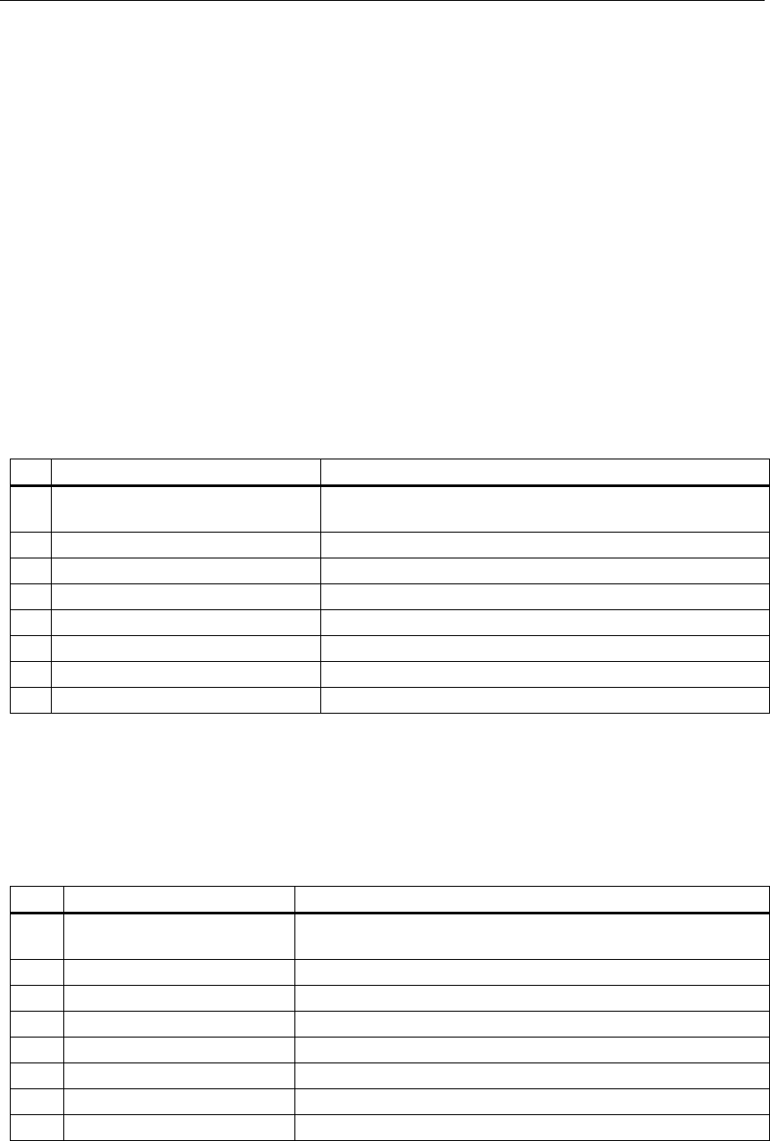
Analog Input Channel
Diagnostic byte for an analog input channel:
Bit Meaning Remarks
0 Configuration/
parameter assignment error
Can be signaled by SFC 52 and EVENTN = W#16#8x50
1 Common mode error Can be signaled by SFC 52 and EVENTN = W#16#8x51
2 P short circuit Can be signaled by SFC 52 and EVENTN = W#16#8x52
3 M short circuit Can be signaled by SFC 52 and EVENTN = W#16#8x53
4 Wire break Can be signaled by SFC 52 and EVENTN = W#16#8x54
5 Reference channel error Can be signaled by SFC 52 and EVENTN = W#16#8x55
6 Current below measuring range Can be signaled by SFC 52 and EVENTN = W#16#8x56
7 Current above measuring range Can be signaled by SFC 52 and EVENTN = W#16#8x57
Analog Output Channel
Diagnostic byte for an analog output channel:
Bit Meaning Remarks
0 Configuration/
parameter assignment error
Can be signaled by SFC 52 and EVENTN = W#16#8x60
1 Common mode error Can be signaled by SFC 52 and EVENTN = W#16#8x61
2 P short circuit Can be signaled by SFC 52 and EVENTN = W#16#8x62
3 M short circuit Can be signaled by SFC 52 and EVENTN = W#16#8x63
4 Wire break Can be signaled by SFC 52 and EVENTN = W#16#8x64
5 0 Reserved
6 No load voltage Can be signaled by SFC 52 and EVENTN = W#16#8x66
7 0 Reserved