TPS3 12 & TPS3 15 Surge Protective Device User Manual - USA
V WARNING - Hazardous Voltage & Shock Hazard Failure to Follow These Instructions Could Result in Death or Serious Injury • • • • • • Only qualified licensed electricians should install or service SPDs Hazardous voltages exist within SPDs SPDs should never be installed or serviced when energized Use appropriate safety precautions including Personal Protection Equipment Failure to follow these instructions can result in death, serious injury, and/or equipment damage.
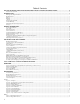
Table of Contents Failure to Follow These Instructions Could Result in Death or Serious Injury............................... 2 Do Not Hi-Pot Test SPDs.............................................................................................................................................................................2 Introduction....................................................................................................................................................
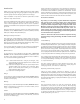
Introduction Thank you for choosing Siemens TPS3 Surge Protective Device (SPD). This is a high quality, high energy surge suppressor designed to protect sensitive equipment from damaging transient overvoltages. Proper installation is important to maximize performance. Please follow the steps outlined herein. This entire User Manual should be read prior to beginning installation. These instructions are not intended to replace national or local codes.
Industry Standards Changes - 2009 General Information UL 1449 Third Edition and 2008 NEC® Article 285 generated substantial changes. Product Family Outline • • • • The term TVSS changed to SPD Types 1, 2, 3 & 4 SPDs are created UL 1449 clamping voltage performance testing changed from 500A to 3,000A UL 1449 added new Nominal Discharge Current testing (I nominal, or In), which consists of more rigorous duty-cycle testing The SPD Type category is important to understand before installing any SPD.
Table 1: Model Number Decoder TPS Series Description TPS3 12 TPS3 L12 TPS3 15 TPS3 L15 Externally mounted SPD, single module in enclosure, standard modes of protection Externally mounted SPD, single module in enclosure, 10 modes of protection Externally mounted SPD, dual replaceable modules in enclosure, standard modes of protection Externally mounted SPD, dual replaceable modules in enclosure, 10 modes of protection available voltages Voltage Codes TPS3 12 √ √ √ √ √ √ √ √ √ √ A = 240/120V Split Phase
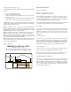
Parallel Connection Pre-Installation and Planning This is a Parallel connected SPD – not series connected. As outlined previously, an SPD ‘drains off’ excessive voltage from an electrical system. Because of parallel connection, installation of the SPD reasonably near the equipment to be protected is satisfactory. Operating Environment Tip: It is very important that wiring leads be configured as short & straight as possible. Avoid long leads. Avoid sharp bends.
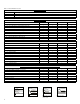
Overcurrent Protection Table 2: Weight & Dimensions TPS3 12 Standard Enclosure Standard Enclosure, 400 – 500kA with Opt. Disc. Switch 4X Non-Metallic 4X Non-Metallic, 400 – 500kA with Opt. Disc. Switch 4X Stainless 4X Stainless, 400 – 500kA with Opt. Disc. Switch Pullbox & Flush mount Pullbox & Flush mount, 400 – 500kA with Opt. Disc. Switch TPS3 15 Internal disconnect switch standard Standard Enclosure 4X Non-Metallic 4X Stainless Pullbox & Flush mount H/W/D (in./mm.) Weight 12" x12" x 7.
Terminals Figure 3: NEMA 3R Drain Holes Terminals will accept 14 - 2 AWG conductor and are provided for line (phase), neutral (if used), and equipment safety ground connections. 8 AWG is the minimum recommended wire size because UL testing and evaluation was performed using 8 AWG. Wire Size and Installation Torque This is a parallel-connected SPD; it is not series-connected. The size of the SPD wiring is independent of the ampere rating of the protected circuit.
Optional Flush Mount Installation Considerations Disconnect Switch (Opt. on TPS3 12, Std. on TPS3 15) The TPS3 12 and TPS3 15 are approximately 6” deep. The unit will not mount flush unless there is at least 6” of depth clearance. The TPS3 12 and TPS3 15 are not designed to mount flush on a typical 2 x 4 stud wall. The disconnect switch provides manual disconnection means for phase conductors and the neutral conductor. Ground is not switched.
V DANGER V CAUTION Hazardous voltage. Will cause death or serious injury. CONDUCTING DIELECTRIC AND/OR HI-POTENTIAL TESTING WILL CAUSE INTERNAL DAMAGE TO TPS3 UNIT. Keep Out. Qualified personnel only. Disconnect and lock off all power before working on this equipment. Do not perform dielectric or high potential tests with the TPS3 unit installed.
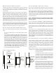
Figure 4: Electrical Drawings Figure 1 Figure 3 Hot (BLK) B Phase B (BLK) A Neutral (WHT) N Hot (BLK) Ground (GRN) C SPLIT 2 Hots, 1 Neu, 1 Grnd } } Ground (GRN) Phase C (BLK) DELTA & HRG WYE 3 Hots, 1 Grnd CAUTION UL R Listed 56E3 Listed R UL R UL Listed A CAUTION TVSS 56E3 TVSS 56E3 N Clearwater, Florida Clearwater, Florida Advanced Protection Technologies, Inc. CAUTION Clearwater, Florida Advanced Protection Technologies, Inc.
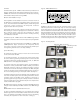
Operation Figure 8: Horizontal Display (Shown with Surge Counter) Diagnostic Display Panel Figure 9: Vertical Display (Shown with Surge Counter) All indicators and controls are located on the diagnostic panel. The diagnostic panel is located on the front of the SPD enclosure or behind the door on certain optional enclosures. Each phase features a Green LED indicator. Green LEDs indicate correct operation.
Dry Contact Option Maintenance Two sets of Form C dry contacts are included with the Dry Contact option. Dry Contacts change state during inoperative conditions, including loss of power. Any status change can be monitored elsewhere via Dry Contacts. SPDs require minimal maintenance. Periodic inspection of diagnostic LED indicators ensures proper operation. Clean SPD as appropriate. A Terminal Block includes two sets of Normally Open (N.O.) and Normally Closed (N.C) contacts.
Display Replacement The display is field replaceable. Deenergize SPD, confirm with appropriate measurement equipment and discharge internal capacitance to ground. Mark locations and carefully disconnect diagnostic cables, contacts, connecting conductors, etc. Unbolt display and replace. Reinstall in reverse. Note that a sealing gasket between the display and the enclosure is a key component ensuring weather resistance. Replace the gasket whenever the display is removed.
Siemens Industry, Inc. Building Technologies Division 5400 Triangle Parkway Norcross, GA 30092 888-333-3545 info.us@siemens.com 6.17.11.