
User's Manual


Getting started with LOGO!
LOGO!
16 Manual, 04/2011, A5E03556174-01
Note
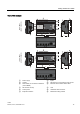
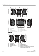
The LOGO! Base Module may only be equipped with expansion modules of the same
voltage class. Mechanical encoding pins in the housing prevent you from connecting devices
of a different voltage class.
Exception: The interface on the left side of an analog module or communication module is
galvanically isolated.
This type of expansion module can therefore be connected to devices of a
different voltage
class (Page
36).
A LOGO! TD, if used, can be connected to only one LOGO! Base Module.
Each LOGO! Base Module supports the following connections for the creation of the circuit
program, regardless of the number of connected modules:
• Digital inputs I1 to I24
• Analog inputs AI1 to AI8
• Digital outputs Q1 to Q16
• Analog outputs AQ1 to AQ2
• Digital flag blocks M1 to M27:
– M8: Startup flag
– M25: Backlight flag: LOGO! onboard display
– M26: Backlight flag: LOGO! TD
– M27: Message text character set flag
• Analog flag blocks: dependent upon the device series
– 0BA6: AM1 to AM6
– 0BA7: AM1 to AM16
• Shift register bits: dependent upon the device series
– 0BA6: S1 to S8
– 0BA7: S1.1 to S4.8 (32 shift register bits)
• 4 cursor keys
• Blank outputs: dependent upon the device series
– 0BA6: X1 to X16
– 0BA7: X1 to X64
LOGO! 0BA7 additionally supports display of the following network digital/analog inputs and
outputs if you have previously configured them in the circuit program in LOGO!Soft Comfort
V7.0 and downloaded the program to the 0BA7 device:
• 64 network digital inputs: NI1 to NI64
• 32 network analog inputs: NAI1 to NAI32
• 64 network digital outputs: NQ1 to NQ64
• 16 network analog outputs: NAQ1 to NAQ16