
User's Manual

Getting started with LOGO!
LOGO!
24 Manual, 04/2011, A5E03556174-01
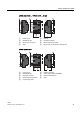
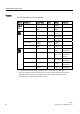
Versions
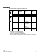
The following LOGO! versions are available:
Symbol Designation Supply voltage Inputs Outputs Properties
LOGO! 12/24RCE 12/24V DC 8 digital
1)
4 relays
(10 A)
(0BA7)
LOGO! 230RCE 115 ... 240 V
AC/DC
8 digital 4 relays
(10A)
LOGO! 12/24RC 12/24 V DC 8 digital
1)
4 relays
(10 A)
LOGO! 24 24 V DC 8 digital
1)
4 solid state
24V / 0.3A
no clock
LOGO! 24C 24 V DC 8 digital
1)
4 solid state
24V / 0.3A
LOGO! 24RC
3)
24 V AC/
24 V DC
8 digital 4 relays
(10A)
LOGO! 230RC
2)
115 ... 240 V
AC/DC
8 digital 4 relays
(10A)
LOGO! 12/24RCo 12/24 V DC 8 digital
1)
4 relays
(10A)
no display unit
no keyboard
LOGO! 24o 24 V DC 8 digital
1)
4 solid state
24 V / 0.3A
no display unit
no keyboard
no clock
LOGO! 24Co 24 V DC 8 digital
1)
4 solid state
24 V / 0.3A
no display unit
no keyboard
LOGO! 24RCo
3)
24 V AC / 24 V DC 8 digital 4 relays
(10A)
no display unit
no keyboard
LOGO! 230RCo
2)
115 ... 240 V
AC/DC
8 digital 4 relays
(10A)
no display unit
no keyboard
1)
Of those can be used alternatively: 4 analog inputs (0 ... 10V) and 4 fast digital inputs.
2)
230 V AC versions: Two groups consisting of 4 inputs each. Each input within a group must be
connected to the same phase. It is possible to interconnect groups with a different phase.
3)
The digital inputs can be operated with P or N action.