
User's Manual

Getting started with LOGO!
LOGO!
Manual, 04/2011, A5E03556174-01
25
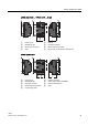
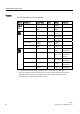
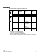
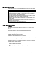
Expansion modules
The following expansion modules can be connected to LOGO!:
Symbol Name Power supply Inputs Outputs
LOGO! DM8 12/24R 12/24 V DC 4 digital 4 relays (5A)
LOGO! DM8 24 24 V DC 4 digital 4 solid state 24V /
0.3A
LOGO! DM8 24R
3)
24 V AC/DC 4 digital 4 relays (5A)
LOGO! DM8 230R 115 ... 240 V AC/DC 4 digital
1)
4 relays (5A)
LOGO! DM16 24 24 V DC 8 digital 8 solid state
24V / 0.3A
LOGO! DM16 24R 24 V DC 8 digital 8 relays (5A)
LOGO! DM16 230R 115 ... 240 V AC/DC 8 digital
4)
8 relays (5A)
LOGO! AM2 12/24 V DC 2 analog
0 ... 10V or
0/4 ... 20mA
2)
None
LOGO! AM2 PT100 12/24 V DC 2 PT100
6)
-50 degrees C to
+200 degrees C
None
LOGO! AM2 RTD 12/24 V DC 2 PT100 or 2 PT1000
or 1 PT100 plus 1
PT1000
6)
-50 degrees C to
+200 degrees C
None
LOGO! AM2 AQ 24 V DC None 2 analog
0 ... 10 V DC or
0/4...20mA
5)
1)
Different phases are not allowed within the inputs.
2)
0 ... 10 V, 0/4 ... 20 mA can be connected optionally.
3)
Digital inputs can be operated either with P or with N action.
4)
Two groups consisting of 4 inputs each. Each input within a group must be connected to the same
phase. It is possible to interconnect groups with a different phase.
5)
0 ... 10 V, 0/4 ... 20 mA can be connected optionally. The 0/4 ... 20 mA current output is only
possible with the LOGO! 0BA6 Base Module.
6)
Sensors supported by the LOGO! AM2 RTD module are the PT100 and PT1000 sensors with a
default temperature coefficient α of 0.003850.