
User's Manual
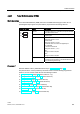

LOGO! functions
4.4 Special functions list - SF
LOGO!
Manual, 04/2011, A5E03556174-01
261
4.4.31 Pulse Width Modulator (PWM)
Short description
The Pulse Width Modulator (PWM) instruction modulates the analog input value Ax to a
pulsed digital output signal. The pulse width is proportional to the analog value Ax.
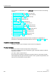
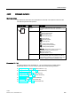
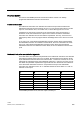
Symbol in LOGO! Wiring Description
Input En A positive edge (0 to 1 transition) at input En enables
the PWM function block.
Input Ax Analog signal to be modulated to a pulsed digital
output signal.
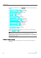
Parameter A: Gain
Range of values: ± 10.00
B: Zero offset
Range of values: ± 10,000
T: Periodic time over which the digital output
is modulated
p: Number of decimals
Range of values: 0, 1, 2, 3
Min:
Range of values: ±20,000
Max:
Range of values: ±20,000
aᇄ
4
(Q
$[
3DU
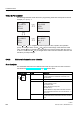
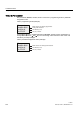
Output Q Q is set or reset for the proportion of each time period
according to the proportion of the standardized value
Ax to the analog value range.
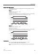
Parameter T
Note the defaults of the T parameters listed in topic Time response (Page 151).
The periodic time T can be provided by the actual value of another already-programmed
function. You can use the actual value of the following functions:
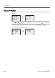
●
Analog comparator (Page 218) (actual value Ax – Ay)
●
Analog threshold trigger (Page 213) (actual value Ax)
●
Analog amplifier (Page 226) (actual value Ax)
●
Analog multiplexer (Page 248) (actual value AQ)
●
Analog Ramp (Page 251) (actual value AQ)
●
Mathematic instruction (Page 265) (actual value AQ)
●
PI controller (Page 256) (actual value AQ)
●
Up/down counter (Page 201) (actual value Cnt)