
User's Manual

Technical data
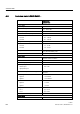
A.2 Technical data: LOGO! 230...
LOGO!
322 Manual, 04/2011, A5E03556174-01
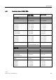
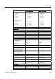
LOGO! 230RC
LOGO! 230RCo
LOGO! 230RCE
Input current at
• Signal 0
• Signal 1
• Signal 0
• Signal 1
• < 0.03 mA AC
• > 0.08 mA AC
• < 0.03 mA DC
• > 0.12 mA DC
• < 0.03 mA AC
• > 0.08 mA AC
• < 0.03 mA DC
• > 0.12 mA DC
Delay time at 0 to 1:
• 120V AC
• 240 V AC
• 120 V DC
• 240V DC
Delay time at 1 to 0:
• 120V AC
• 240 V AC
• 120 V DC
• 240V DC
• typ. 50 ms
• typ. 30 ms
• typ. 25 ms
• typ. 15 ms
• typ. 65 ms
• typ. 105 ms
• typ. 95 ms
• typ. 125 ms
• typ. 50 ms
• typ. 30 ms
• typ. 25 ms
• typ. 15 ms
• typ. 65 ms
• typ. 105 ms
• typ. 95 ms
• typ. 125 ms
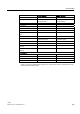
Line length (unshielded) max. 100 m max. 100 m
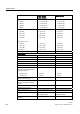
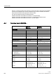
Digital outputs
Number 4 4
Output type Relay outputs Relay outputs
Electrical isolation Yes Yes
In groups of 1 1
Control of a digital input Yes Yes
Continuous current I
th
max. 10 A per relay max. 10 A per relay
Surge current
Incandescent lamp load (25000
switching cycles) at
• 230/240 V AC
• 115/120 V AC
max. 30 A
• 1000 W
• 500 W
max. 30 A
• 1000 W
• 500 W
Fluorescent tubes with ballast
(25000 switching cycles)
10 x 58 W (at 230/240 V AC) 10 x 58 W (at 230/240 V AC)
Fluorescent tubes, conventionally
compensated (25000 switching
cycles)
1 x 58 W (at 230/240 V AC) 1 x 58 W (at 230/240 V AC)
Fluorescent tubes, uncompensated
(25000 switching cycles)
10 x 58 W (at 230/240 V AC) 10 x 58 W (at 230/240 V AC)
Short circuit-proof cos 1 Power protection B16, 600A Power protection B16, 600A
Short circuit-proof cos 0.5 to 0.7 Power protection B16, 900A Power protection B16, 900A
Derating none; across the entire
temperature range
none; across the entire
temperature range
Parallel output circuits for power
increase
Not permitted Not permitted