
User's Manual

Technical data
A.4 Technical data: LOGO! 24...
LOGO!
326 Manual, 04/2011, A5E03556174-01
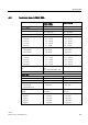
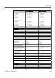
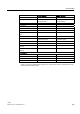
Notice: For fluorescent lamps with capacitors, the technical data of fluorescent lamp ballasts
must also be considered. If the maximum allowed surge current is exceeded, fluorescent
lamps must be switched with appropriate contactor relays.
The data was determined with the following devices:
Siemens fluorescent tubes 58W VVG 5LZ 583 3-1 uncompensated.
Siemens fluorescent tubes 58W VVG 5LZ 583 3-1 parallel compensated with 7μF.
Siemens fluorescent tubes 58W VVG 5LZ 501 1-1N with ballast.
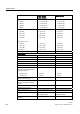
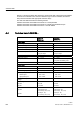
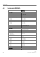
A.4 Technical data: LOGO! 24...
LOGO! 24
LOGO! 24o
LOGO! 24C
LOGO! 24Co
Power supply
Input voltage 24 V DC 24 V DC
Permissible range 20.4 ... 28.8 V DC 20.4 ... 28.8 V DC
Reverse polarity protection Yes Yes
Permissible mains frequency - - - -
Power consumption from 24 V DC 40 ... 75 mA
0.3 A per output
40 ... 75 mA
0.3 A per output
Voltage failure buffering
Power loss at 24 V 1.0 ... 1.8 W 1.0 ... 1.8 W
Backup of the real-time clock at 25
°C
no clock available typ. 80 hours without battery card
typ. 2 years with battery card
Accuracy of the real-time clock no clock available typ. ± 2 s / day
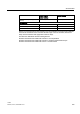
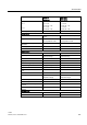
Digital inputs
Number 8 8
Electrical isolation No No
Numbef of high speed inputs 4 (I3, I4, I5, I6) 4 (I3, I4, I5, I6)
Input frequency
• Normal input
• High speed input
• max. 4 Hz
• max. 5 kHz
• max. 4 Hz
• max. 5 kHz
Max. continuous permissible
voltage
28.8 V DC 28.8 V DC
Input voltage
Signal 0
Signal 1
L+
< 5 V DC
> 12 V DC
L+
< 5 V DC
> 12 V DC
Input current at
Signal 0
Signal 1
< 0.85 mA (I3...I6)
< 0.05 mA (I1, I2, I7, I8)
> 2 mA (I3... I6)
> 0.15 mA (I1, I2, I7, I8)
< 0.85 mA (I3...I6)
< 0.05 mA (I1, I2, I7, I8)
> 2 mA (I3... I6)
> 0.15 mA (I1, I2, I7, I8)