
User's Manual

Technical data
A.4 Technical data: LOGO! 24...
LOGO!
Manual, 04/2011, A5E03556174-01
327
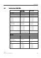
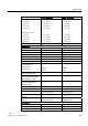
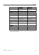
LOGO! 24
LOGO! 24o
LOGO! 24C
LOGO! 24Co
Delay time at
0 to 1
1 to 0
typ. 1.5 ms
<1.0 ms (I3 ... I6)
typ. 1.5 ms
<1.0 ms (I3 ... I6)
typ. 1.5 ms
<1.0 ms (I3 ... I6)
typ. 1.5 ms
<1.0 ms (I3 ... I6)
Line length (unshielded) max. 100 m max. 100 m
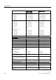
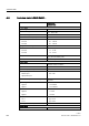
Analog inputs
Number 4 (I1=AI3, I2=AI4, I7=AI1,
I8=AI2)
4 (I1=AI3, I2=AI4, I7=AI1, I8=AI2)
Range 0 ... 10 V DC
input impedance 72 kΩ
0 ... 10 V DC
input impedance 72 kΩ
Cycle time for analog value
generation
300 ms 300 ms
Line length (shielded and twisted) max. 10 m max. 10 m
Error limit ± 1.5% at FS ± 1.5% at FS
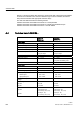
Digital outputs
Number 4 4
Output type Transistor,
current-sourcing
1)
Transistor,
current-sourcing
1)
Electrical isolation No No
In groups of - - - -
Control of a digital input Yes Yes
Output voltage ≤ Supply voltage ≤ Supply voltage
Output current max. 0.3 A max. 0.3 A
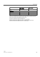
Short circuit-proof and overload-
proof
Yes Yes
Short circuit current limitation Approx. 1 A Approx. 1 A
Derating none; across the entire
temperature range
none; across the entire
temperature range
Short circuit-proof cos 1 - - - -
Short circuit-proof cos 0.5 to 0.7 - - - -
Parallel output circuit for power
increase
Not permitted Not permitted
Protection of output relay (if
desired)
- - - -
Switching rate
2)
Mechanical - - - -
Electrical 10 Hz 10 Hz