
User's Manual

Technical data
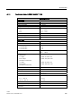
A.7 Technical data: LOGO! DM8 24R and LOGO! DM16 24R
LOGO!
Manual, 04/2011, A5E03556174-01
333
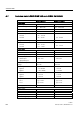
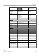
LOGO! DM8 24R LOGO! DM16 24R
Continuous current I
th
max. 5 A per relay max. 5 A per relay
Surge current max. 30 A max. 30 A
Incandescent lamp load (25000
switching cycles) at
1000 W 1000 W
Fluorescent tubes with ballast
(25000 switching cycles)
10 x 58 W 10 x 58 W
Fluorescent tubes,
conventionally compensated
(25000 switching cycles)
1 x 58 W 1 x 58 W
Fluorescent tubes,
uncompensated (25000
switching cycles)
10 x 58 W 10 x 58 W
Derating none; across the entire
temperature range
none; across the entire
temperature range
Short circuit-proof cos 1 Power protection B16, 600A Power protection B16, 600A
Short circuit-proof cos 0.5 to 0.7 Power protection B16, 900A Power protection B16, 900A
Parallel output circuits for power
increase
Not permitted Not permitted
Protection of output relay (if
desired)
max. 16 A,
characteristic B16
max. 16 A,
characteristic B16
Switching rate
Mechanical 10 Hz 10 Hz
Ohmic load/lamp load 2 Hz 2 Hz
Inductive load 0.5 Hz 0.5 Hz
Notice: For fluorescent lamps with capacitors, the technical data of fluorescent lamp ballasts
must also be considered. If the maximum allowed surge current is exceeded, fluorescent
lamps must be switched with appropriate contactor relays.
The data was determined with the following devices:
Siemens fluorescent tubes 58W VVG 5LZ 583 3-1 uncompensated.
Siemens fluorescent tubes 58W VVG 5LZ 583 3-1 parallel compensated with 7μF.
Siemens fluorescent tubes 58W VVG 5LZ 501 1-1N with ballast.