
User's Manual

Technical data
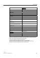
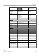
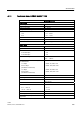
A.8 Technical data: LOGO! 12/24... LOGO! DM8 12/24R
LOGO!
Manual, 04/2011, A5E03556174-01
335
LOGO! 12/24RC
LOGO! 12/24RCo
LOGO! 12/24RCE
LOGO! DM8 12/24R
Input current at
• Signal 0
• Signal 1
< 0.85 mA (I3...I6)
< 0.05 mA (I1, I2, I7, I8)
> 1.5 mA (I3... I6)
> 0.1 mA (I1, I2, I7, I8)
< 0.85 mA
> 1.5 mA
Delay time at
• 0 to 1
• 1 to 0
typ. 1.5 ms
<1.0 ms (I3 ... I6)
typ. 1.5 ms
<1.0 ms (I3 ... I6)
typ. 1.5 ms
typ. 1.5 ms
Line length (unshielded) max. 100 m max. 100 m
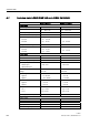
Analog inputs
Number 4 (I1=AI3, I2=AI4, I7=AI1, I8=AI2) - -
Range 0 ... 10 V DC
input impedance 72 kΩ
- -
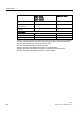
Cycle time for analog value
generation
300 ms - -
Line length (shielded and
twisted)
max. 10 m - -
Error limit ± 1.5 % at FS - -
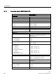
Digital outputs
Number 4 4
Output type Relay outputs Relay outputs
Electrical isolation Yes Yes
In groups of 1 1
Control of a digital input Yes Yes
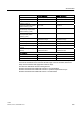
Continuous current I
th (per
terminal)
max. 10 A per relay max. 5 A per relay
Surge current max. 30 A max. 30 A
Incandescent lamp load
(25000 switching cycles) at
1000 W 1000 W
Fluorescent tubes with
ballast (25000 switching
cycles)
10 x 58 W 10 x 58 W
Fluorescent tubes,
conventionally compensated
(25000 switching cycles)
1 x 58 W 1 x 58 W
Fluorescent tubes,
uncompensated (25000
switching cycles)
10 x 58 W 10 x 58 W
Derating none; across the entire temperature
range
none; across the entire
temperature range
Short circuit-proof cos 1 Power protection B16, 600A Power protection B16, 600A