
User's Manual

LOGO! installation and wiring
2.3 Wiring LOGO!
LOGO!
Manual, 04/2011, A5E03556174-01
49
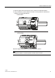
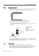
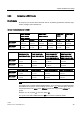
2.3.3 Connecting LOGO! inputs
Requirements
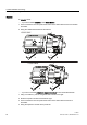
At the inputs you connect sensor elements such as: momentary pushbuttons, switches, light
barriers, daylight control switches etc.
Sensor characteristics for LOGO!
LOGO! 12/24RCE
LOGO! 12/24RC
LOGO! 12/24RCo
LOGO! 24/24o
LOGO! 24C/24Co
LOGO! DM8
12/24R
LOGO! DM8
24
I3 ... I6 I1,I2,I7,I8 I3 ... I6 I1,I2,I7,I8 I1 ... I8 I1 ... I8
Signal status 0
Input current
< 5 V DC
< 0.85 mA
< 5 V DC
< 0.05 mA
< 5 V DC
< 0.85 mA
< 5 V DC
< 0.05 mA
< 5 V DC
< 0.85 mA
< 5 V DC
< 0.85 mA
Signal status 1
Input current
> 8.5 V DC
> 1.5 mA
> 8.5 V DC
> 0.1 mA
> 12 V DC
> 2 mA
> 12 V DC
> 0.15 mA
> 8.5 V DC
> 1.5 mA
> 12 V DC
> 2 mA
LOGO! 24RC (AC)
LOGO! 24RCo (AC)
LOGO! DM8 24R (AC)
LOGO! 24RC (DC)
LOGO! 24RCo (DC)
LOGO! DM8 24R (DC)
LOGO! 230RCE (AC)
LOGO! 230RC (AC)
LOGO! 230RCo (AC)
LOGO! DM8 230R (AC)
LOGO!230RCE (DC)
LOGO! 230RC (DC)
LOGO! 230RCo (DC)
LOGO! DM8 230R (DC)
Signal status 0
Input current
< 5 V AC
< 1.0 mA
< 5 V DC
< 1.0 mA
< 40 V AC
< 0.03 mA
< 30 V DC
< 0.03 mA
Signal status 1
Input current
> 12 V AC
> 2.5 mA
> 12 V DC
> 2.5 mA
> 79 V AC
> 0.08 mA
> 79 V DC
> 0.08 mA
LOGO! DM16 24R LOGO! DM16 24 LOGO! DM16 230R (AC) LOGO! DM16 230R (DC)
Signal status 0
Input current
< 5 V DC
< 1.0 mA
< 5 V DC
< 1.0 mA
< 40 V AC
< 0.05 mA
< 30 V DC
< 0.05 mA
Signal status 1
Input current
> 12 V DC
> 2.0 mA
> 12 V DC
> 2.0 mA
> 79 V AC
> 0.08 mA
> 79 V DC
> 0.08 mA
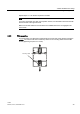
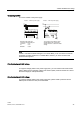
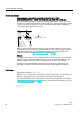
Note
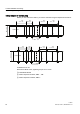
The digital inputs of LOGO! 230RCE/230RC/230RCo and of expansion module DM16 230R
are divided into two groups, each consisting of four inputs. Within the same group, all inputs
must be operated on the same phase. Different phases are only possible between the
groups.
Example: I1 to I4 on phase L1, I5 to I8 on phase L2.
The inputs of the LOGO! DM8 230R must not be connected to different phases.