
User's Manual

LOGO! installation and wiring
2.3 Wiring LOGO!
LOGO!
52 Manual, 04/2011, A5E03556174-01
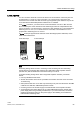
Sensor connections
To connect sensors to LOGO! :
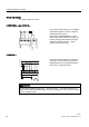
LOGO! 12/24.... and LOGO! 24...
0/ , , , , , ,
/
0
The inputs of these devices are not isolated
and therefore require a common reference
potential (chassis ground).
With LOGO! 12/24RCE/RC/RCo, LOGO!
24/24o and LOGO! 24C/24Co modules, you
can tap analog signals between the supply
voltage and chassis ground (* = series
resistor (6.6 kΩ) at 24 V DC).
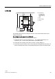
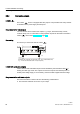
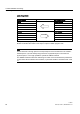
LOGO! 230....
/
/
/
1
1/ , , , , , ,
The inputs of these devices are arranged in
two groups, each consisting of four inputs.
Different phases are only possible between
blocks, but not within the blocks.
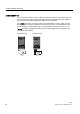
WARNING
Current safety regulations (VDE 0110, ... and IEC 61131-2, ... as well as cULus) do not
permit the connection of different phases to an AC input group (I1 to I4 or I5 to I8) or to the
inputs of a digital module.