
User's Manual

LOGO! installation and wiring
2.3 Wiring LOGO!
LOGO!
Manual, 04/2011, A5E03556174-01
53
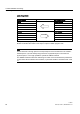
LOGO! AM2
8 , 0 8, 0
5816723
/
0
/
/
0
0
0
3(
/ 0 / 0
ཱ
ི
9
9ROWDJHPHDVXUHPHQW
&XUUHQWPHDVXUHPHQW
5HIHUHQFH
&XUUHQW
&XUUHQW
P$
6HQVRU
3( 3(WHUPLQDOIRU
FRQQHFWLQJHDUWK
DQGVKLHOGLQJWKH
DQDORJPHDVXULQJ
FDEOH
(DUWK
ཱ &DEOHVKLHOGLQJ
ི ',1UDLO
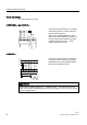
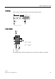
The illustration above shows an example of four-wire current measurement and two-wire
voltage measurement.
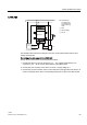
Connecting a two-wire sensor to the LOGO! AM2
Wire up the two-wire sensor's connecting wires as follows:
1. Connect the sensor's output to connection U (0 ... 10 V voltage measurement) or to
connection I (0/4 ... 20 mA current measurement) of the AM2 module.
2. Connect the plus connector on the sensor to the 24 V supply voltage (L+).
3. Connect the ground connection of the current output M (on the right side of the sensor, as
shown in the figure above) to the corresponding M input (M1 or M2) on the AM2 module.