
User's Manual

LOGO! installation and wiring
2.3 Wiring LOGO!
LOGO!
Manual, 04/2011, A5E03556174-01
55
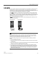
LOGO! AM2 RTD
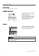
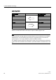
You can connect a maximum of two PT100 sensors or two PT1000 or one PT100 plus one
PT1000 sensor in a 2-wire or 3-wire connection or in a mixed use of 2-wire and 3-wire
connection to the module. Note that the sensor type supported by the module is only PT100
or PT1000 with the default temperature coefficient of α= 0.003850.
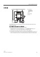
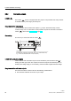
For a 2-wire connection, you need to short-circuit terminals M1+ and IC1 or M2+ and IC2.
Errors caused by the ohmic resistance of the measuring line are not compensated for this
type of connection. If a PT100 sensor is connected, a line resistance of 1 Ω is proportional to
measuring error of +2.5 °C; if a PT1000 sensor is connected, a line resistance of 1 Ω is
proportional to measuring error of +0.25 °C.
A 3-wire technique suppresses the influence of the cable length (ohmic resistance) on the
result of the measurement.
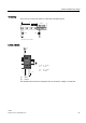
3737
3737
/ 0 / 0
3(
5816723
0 ,& 0 0,& 0
/ 0 / 0
3(
5816723
0 ,& 0 0,& 0
ZLUHWHFKQLTXH
ZLUHWHFKQLTXH
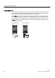
Note
Fluctuating analog values are due to screening on the connecting wire from the analog
valuator device to the analog AM2 / AM2 PT100 / AM2 RTD LOGO! expansion module
(encoder wire) that has either been mounted incorrectly or not at all.
To avoid fluctuating analog values when using these expansion modules, proceed as
follows:
• Use only shielded encoder wires.
• Shorten the encoder wire as much a possible. The encoder wire must not be more than
10 meters long.
• Clamp the encoder wire on one side only and clamp it only to the PE terminal on the AM2
/ AM2 PT100 / AM2 AQ / AM2 RTD expansion module.
• Connect ground on the encoder supply to the PE terminal on the expansion module.
• Avoid operating the LOGO! AM2 PT100 or LOGO! AM2 RTD expansion module with a
power supply that is not grounded (potential-free). If you cannot avoid this, connect the
negative output/ground output on the power supply to the shielding on the resistance
thermometer's measuring wires.