
User's Manual

LOGO! installation and wiring
2.3 Wiring LOGO!
LOGO!
60 Manual, 04/2011, A5E03556174-01
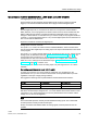
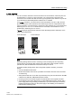
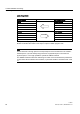
Logic Assignments
LOGO! system AS Interface system
Inputs Output data bits
I
n
DQ1
I
n+1
DQ2
I
n+2
DQ3
I
n+3
DQ4
Outputs Input data bits
Q
n
DI1
Q
n+1
DI2
Q
n+2
DI3
Q
n+3
DI4
"n" depends on the plug-in position of the expansion module relative to the LOGO! Base
Module. It indicates the number of the input or output in LOGO! program code.
Note
Ensure that there is enough space for the inputs/outputs of the AS interface in the LOGO!'s
address space. If you are already using more than 12 physical outputs or more than 20
physical inputs, it is no longer possible to operate the CM AS interface!
For detailed information about the networking of LOGO! on the AS interface bus please refer
to the LOGO! CM
A
S Interface documentation, in particular the Micro Automation Sets 7 and
16.