
User's Manual
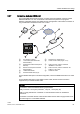


LOGO! installation and wiring
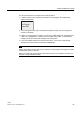
2.4 Putting into operation
LOGO!
Manual, 04/2011, A5E03556174-01
67
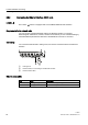
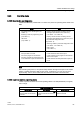
2.4.3 Operating states
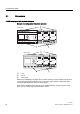
LOGO! Base Module operating states
LOGO! Base Modules (LOGO! Basic or LOGO! Pure) have two operating states: STOP and
RUN.
STOP RUN
• The display shows: 'No Program' (not
LOGO!...o)
• Switching LOGO! to programming mode
(not LOGO!...o)
• LED is red
(only LOGO!...o)
• Display: Screen mask for monitoring I/O and
messages (after START in the main menu)
(not LOGO!...o or LOGO!...E)
• Display: Screen mask for monitoring I/O and
messages (after START in the main menu) or for
the parameter assignment menu
(only LOGO!...E)
• Switching LOGO! to parameter assignment mode
(not LOGO!...o or LOGO!...E)
• LED is green
(only LOGO!...o)
Action of LOGO!:
• The input data is not read.
• The circuit program is not executed.
• The relay contacts are permanently open
or the solid-state outputs are switched off.
Action of LOGO!:
• LOGO! reads the status of the inputs.
• LOGO! uses the circuit program to calculate the
status of the outputs.
• LOGO! switches the relay/solid-state outputs on
or off.
Note
After switching the power on, the system briefly switches through the outputs on the LOGO
24/24o or LOGO! 24C/24Co. With an open circuit, a voltage of > 8 V can occur for up to
approximately 100 ms; when loaded, this time reduces to a matter of microseconds.
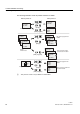
LOGO! expansion modules, operating states
LOGO! expansion modules have three operating states: The LED (RUN/STOP) is lit green,
red or orange.
LED (RUN/STOP) is lit
Green (RUN) Red (STOP) Orange/Yellow
The expansion module
communicates with the device
to the left.
The expansion module does not
communicate with the device to
its left.
Initialization phase of the
expansion module