
User's Manual

Programming LOGO!
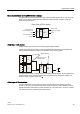
3.1 Connectors
LOGO!
72 Manual, 04/2011, A5E03556174-01
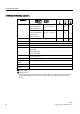
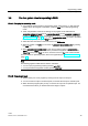
LOGO! has the following connectors :
Connectors
/2*2%$
/2*2%$
'0
$0
$0$4
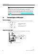
LOGO! 230RCE
LOGO! 230RC/RCo
LOGO! 24RC/RCo
Two groups:
I1 to I4 and I5 to I8
I9 to I24 AI1 to
AI8
Inputs
LOGO! 12/24RCE
LOGO! 12/24RC/RCo
LOGO! 24/24o
LOGO! 24C/24Co
I1, I2, I3-I6, I7, I8
AI3, AI4 ... AI1, AI2
I9 to I24 AI5 to
AI8
none
Outputs Q1 to Q4 Q5 to Q16 none AQ1,
AQ2
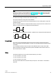
lo Logical '0' signals (off)
hi Logical '1' signals (on)
x An existing connection that is not used
Flags Digital flags: M1 to M27
Analog flags:
AM1to AM6 (0BA6)
AM1to AM16 (0BA7)
Shift register bits S1 to S8 (0BA6)
S1.1 to S4.8 (0BA7)
Network inputs
1)
NI1 to NI64 (0BA7 only)
Network analog
inputs
1)
NAI1 to NAI32 (0BA7 only)
Network outputs
1)
NQ1 to NQ64 (0BA7 only)
Network analog
outputs
1)
NAQ1 to NAQ16 (0BA7 only)
DM: Digital module
AM: Analog module
1)
To make these four connectors available in a LOGO! 0BA7, you must configure them in the circuit
program with LOGO!Soft Comfort V7.0 and download the circuit program to the LOGO! 0BA7
device.