Synco – Application Guide Combination of the devices to a system www.siemens.
Contents Introduction...................................................................................................................4 Advantages offered by combined applications.........................................................5 The communication concept.......................................................................................6 Makeup of plant descriptions......................................................................................8 Plant descriptions: 1.
Introduction Purpose of this document This document describes Synco’s communication concept on the basis of 8 plant descriptions and specifies for every device the settings required for enabling communication. The document can be used as a tutorial or commissioning tool for combined Synco applications.
Advantages offered by combined applications Systems with interconnected Synco devices enable the individual devices to communicate with each other, offering a number of advantages: Energy savings thanks to demand-based control The most energy-efficient control systems generate heat or refrigeration only when a consumer calls for heat or cooling energy.
The communication concept Communication in the Synco system is based on the KNX standard. This means that the devices communicate in KNX LTE mode (LTE = Logical Tag Extended) with which bus communication can be established – with no need for using a software tool. This mode represents a simple method to build up communication. LTE mode makes use of zone addresses. Process values are exchanged between all devices located in the same zone.
• ACS path: … > Plant > Update device list / Edit device list > Address assignment > Enter device address • RDG settings: P81 = Enter device address With the buttons of the RDG room thermostats and Synco 700 devices, or the RMZ790 / RMZ791 operator units, only the device addresses can be set. To set the area and line addresses, the ACS790 software is required. The RXB / RXL room controllers can be addressed via the ACS790 or via the Handy Tool QAX34.3.
Makeup of plant descriptions The plants contained in this document consist of individual applications a detailed description of which is given on the application sheets. This document only describes the relevant communication settings that ensure optimum communication between the individual devices. The application sheets can be downloaded from Siemens’ HVAC Integrated Tool (HIT) via the internet address given above.
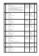
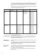
No. 1 Description Applications Controllers Variable air volume (VAV) control with RDG room thermostats CBA001 U2B HQ RMU720B DHW heating HB0001 H6B HQ RMH760B Production of chilled water ADCE06 U2B HQ RMB795B Central air handling (temperature and pressure control of supply air): The supply air temperature setpoint and the pressure setpoints are shifted depending on demand TB0001 DG4 HQ RDG400KN TBZB01 DG4 HQ GDB181.
The plant descriptions are examples and can be extended as required, but adherence to the rules of the KNX standard must be ensured. As shown by the following table, it is also possible to use other standard applications in place of the plant sections used here. The respective application sheets can be downloaded from Siemens’ HVAC Integrated Tool (HIT) via the internet address given above.
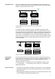
If the room occupancy times of the various geographical zones are identical, a time switch can be defined as the master. Then, the other controllers as time switch slaves adopt the occupancy times from the master. 3150Z07en Geographical zone RM.. RM.. Time switch Time switch Ventilation 1 Heating circuit 2 Geogr zone = 1 Geogr zone = --- TS slave (Apartm.) = --- TS slave (Apartm.) = 1 Slave Master Setting the geographical zone with identical room occupancy times but different operating modes.
1. Variable air volume (VAV) control with RDG room thermostats Partial air conditioning plant for rooms where the room temperature shall be kept constant by heating or cooling the supply air and by controlling the supply air volume. This plant description describes a complete application with 2 rooms, covering the generation of heat or refrigeration and its consumption by the air heating or air cooling coil.
Topology RMB795B No standard application available RMU720B ADCE06 U2B HQ (basic type P) RMH760B HB0001 H6B HQ (basic type H4-0) RDG400KN TB0001 DG4 HQ GDB181.1E/KN RMU720B CBA001 U2B HQ (basic type C) RDG400KN GDB181.
Function description Description of functions Synchronization of clock time The clock time can be set on any of the Synco 700 controllers (RMH, RMU) and is synchronized throughout the system. The clock time can also be displayed on the room thermostats (RDG). Time switch Geographical zone The time switch master – in this case the central control unit (RMB) – forwards the Comfort, Precomfort and Economy modes to all room thermostats (RDG) in its geographical zone.
Parameter settings for communication Parameter Setting Function Remarks 1. Parameter settings on the refrigeration controller, RMU720B, basic type C Basic settings Path: ...
Parameter Setting Function Remarks Settings for the distribution zones Path: ...
Parameter Setting Function Remarks 5. Parameter settings on room thermostat 1, RDG400KN Settings for the zones Path: ... > Communication P82 - geographical zone (apartm) 4 Room group number P83 - geographical zone (room) 2 Room number P87 - air distribution zone 1 Air distribution zone Consecutive numbering 1-x when there are several RDG in the same room group 6. Parameter settings on on VAV controller supply air, GDB181.1E/KN Parameter settings Path: ...
2. 2-pipe fan coil units with heating / cooling changeover and RXB room controllers Partial air conditioning plant for rooms where the room temperature shall be kept constant by heating or cooling the supply air. This plant description describes a complete application with 2 rooms, covering the generation of heat or refrigeration, 2-pipe flow temperature control and 2-pipe fan coil units in the 2 rooms.
Topology RMB795B No standard application available RMU710B C0B001 U1B HQ (basic type C) RMH760B HB0001 H6B HQ (basic type H4-0) RXB22.1/FC12 XFNC03 B22 HQ RMS705B No standard application available RXB21.
Communication settings Generation of refrigeration / heat Zones / settings Prerequisites / assumptions Basic settings Room / room group Distribution zones Function description Clock time master Time switch master Holidays / special day master Clock time operation Remote setting clock slave Fault remote reset Geographical zone Time switch slave Outside temperature zone Heat distribution zone Heat distribution zone source side Refrigeration distribution zone Refrigeration distribution zone source side F
Parameter settings for communication Parameter Setting Function Remarks 1. Parameter settings on the refrigeration controller, RMS705B Basic settings Path: ...
Parameter Setting Function Remarks Settings for the distribution zones Path: ...
Parameter Setting Function Remarks 5. Parameter settings on room controller 1, RXB22.1/FC-12 Settings for the zones Path: ...
3. 4-pipe fan coil units with RXB room controllers Partial air conditioning plant for rooms where the room temperature shall be kept constant by heating or cooling the supply air. This plant description describes a complete application with 2 rooms, covering the generation of heat or refrigeration and 4-pipe fan coil units in 2 rooms. The water temperature in the fan coil units is controlled according to the demand for heat or cooling energy from the rooms.
Topology RMB795B No standard application available RXB21.1/FC10 XFNC04 B21 HQ RMH760B HB0001 H6B HQ (basic type H4-0) RMS705B No standard application available Communication diagram RXB21.
Function description Description of functions Synchronization of clock time Optimization of energy usage room The clock time can be set on any of the Synco 700 controllers (RMH, RMS, RMB) and is synchronized throughout the system. Heat distribution zone When the room calls for heat, the room controller (RXB) forwards a heat request to the central control unit (RMB) via heat distribution zone 2.
Parameter Setting Function Remarks 2. Parameter settings on the heating controller, RMH760B, basic type H4-0 Basic settings Path: ... > Commissioning > Communication > Basic settings Clock time operation Slave The device receives the time of day from the master Remote setting clock slave Yes The master’s clock can be set from this device Remote reset of fault Yes Faults of other bus users can be acknowledged and reset from this device Settings for the distribution zones Path: ...
Parameter Setting Function 4. Parameter settings on room controller 1, RXB21.1/FC-10 Settings for the zones Path: ...
4. 2-pipe fan coil units with heating / cooling changeover and RDG room thermostats Partial air conditioning plant for rooms where the room temperature shall be kept constant by heating or cooling the supply air. This plant description describes a complete application with 2 rooms, covering the generation of heat or refrigeration, 2-pipe flow temperature control and 2-pipe fan coil units in the 2 rooms.
Topology RMB795B No standard application available RMU710B C0B001 U1B HQ (basic type C) RMH760B HB0001 H6B HQ (basic type H4-0) RDG100KN TAAA01 DG1 HQ RMS705B No standard application available RDG100KN TAAB01 DG1 HQ Communication diagram Generation of refrigeration / heat Data points RMS705B Room temperature sensor Outside temperature sensor Heating / cooling changeover Time of day Time switch Holdays / special days Outside temperature Heat request Refrigeration request RMH760B Flow temperature con
Function description Description of functions Synchronization of clock time The clock time can be set on any of the Synco 700 controllers (RMH, RMU, RMS, RMB) and is synchronized throughout the system. The clock time can also be displayed on the room thermostats (RDG). Time switch ture controller (RMU, basic type C) via heat distribution zone 2.
Parameter Setting Function Remarks Settings for the distribution zones Path: ...
Parameter Setting Function Remarks 4. Parameter settings on the central control unit RMB795B Basic settings Path: ...
5. 4-pipe fan coil units with RDG room thermostats Partial air conditioning plant for rooms where the room temperature shall be kept constant by heating or cooling the supply air. This plant description describes a complete application with 2 rooms, covering the generation of heat or refrigeration and 4-pipe fan coil units in the 2 rooms. The water temperature in the fan coil units is controlled according to the demand for heat or cooling energy from the rooms.
Topology RMB795B No standard application available RDG100KN TABA01 DG1 HQ RMH760B HB0001 H6B HQ (basic type H4-0) RDG100KN TABB01 DG1 HQ RMS705B No standard application available Communication diagram Generation of refrigeration / heat Data points Room temperature sensor Outside temperature sensor Supply air temperature sensor Time of day Time switch Holdays / special days Outside temperature Heat request Refrigeration request RMS705B Central control unit RMH760B RMB795B Basic settings Room / ro
Function description Description of functions Synchronization of clock time Outside temperature The clock time can be set on any of the Synco 700 controllers (RMH, RMS, RMB) and is synchronized throughout the system. Outside temperature zone The clock time can also be displayed on the room thermostats (RDG). The central control unit (RMB) distributes the outside temperature in outside temperature zone 1. All devices in outside temperature zone 1 operate with the same outside temperature.
Parameter Setting Function Remarks 2. Parameter settings on the heating controller, RMH760B, basic type H4-0 Basic settings Path: ... > Commissioning > Communication > Basic settings Clock time operation Slave The device receives the time of day from the master Remote setting clock slave Yes The master’s clock can be set from this device Remote reset of fault Yes Faults of other bus users can be acknowledged and reset from this device Settings for the distribution zones Path: ...
Parameter Setting Function Remarks 5. Parameter settings on room thermostat 2, RDG100KN Settings for the zones Path: ...
6. Chilled / heated ceiling and radiator with heating / cooling changeover and RDG room thermostats Partial air conditioning plant for rooms where the room temperature shall be kept constant by a chilled / heated ceiling and a radiator. This plant description describes a complete application with 2 rooms, covering the generation of heat or refrigeration, 2-pipe flow temperature control, chilled / heated ceilings and radiators in the 2 rooms.
Topology RMB795B No standard application available RMU710B C0B001 U1B HQ (basic type C) RMH760B HB0001 H6B HQ (basic type H4-0) RDG100KN TE0001 DG1 HQ RMU720B CBA001 U2B HQ (basic type C) RDG100KN TE0002 DG1 HQ Communication diagram Generation of refrigeration / heat Data points RMU720B Room temperature sensor Outside temperature sensor Heating / cooling changeover Time of day Time switch Holdays / special days Outside temperature Heat request Refrigeration request RMH760B Flow temperature control
Function description Description of functions Synchronization of clock time The clock time can be set on any of the Synco 700 controllers (RMH, RMU, RMB) and is synchronized throughout the system. The clock time can also be displayed on the room thermostats (RDG). Time switch ture controller (RMU, basic type C) via heat distribution zone 2.
Parameter Setting Function Remarks Settings for the distribution zones Path: ...
Parameter Setting Function Remarks Settings for the distribution zones Path: ...
Parameter Setting Function Remarks 5. Parameter settings on room thermostat 1, RDG100KN Settings for the zones Path: ...
7. Supply air temperature control with RMU universal controllers Ventilation plant for rooms where the room temperature shall be kept constant by heating the supply air. This plant description describes a complete application with 2 partial ventilation plants, covering the generation of heat and its distribution to the air heating coils. The supply air temperature is controlled depending on the demand for heat.
Communication diagram Generation of heat Distribution of heat Data points Room temperature sensor Outside temperature sensor Time of day Time switch Holidays / special days Outside temperature Heat request RMH760B Ventilation plants RMH760B X = transmitter Communication settings RMU710B X X = receiver Generation of Distribution of heat heat Prerequisites / assumptions Basic settings Room / room group Holidays / special days Distribution zones Function description RMU710B Zones / settings Clo
Parameter settings for communication Parameter Setting Function Remarks 1. Parameter settings on the heating controller, RMH760B, basic type H4-0 Basic settings Path: ...
Parameter Setting Function Remarks Settings for holidays/special days Path: ... > Commissioning > Communication > Holidays/special days Holidays / special day operation Master The device forwards the information about holidays and special days to all slave bus users in the same holidays / special day zone Holidays / special day zone 1 The device sends the information about holidays and special days in holidays / special day zone 1 Settings for the distribution zones Path: ...
8. Supply air temperature control with heating / cooling changeover and RMU universal controllers Partial air conditioning plant for rooms where the room temperature shall be kept constant by heating or cooling the supply air. This plant description describes a complete application with a ventilation plant, covering the generation of heat or refrigeration and its distribution to the air heating or air cooling coil.
Communication diagram Generation of refrigeration / heat Data points Room temperature sensor Outside temperature sensor Heating / cooling changeover Time of day Outside temperature Heat request Refrigeration request RMS705B Flow temperature control Ventilation plant RMU710B RMU720B X X RMH760B X = transmitter Communication settings Generation of refrigeration / heat Prerequisites / assumptions Basic settings Distribution zones Function description = receiver Zones / settings Clock time master
Parameter settings for communication Parameter Setting Function Remarks 1. Parameter settings on the refrigeration controller, RMS705B Basic settings Path: ...
Parameter Setting Function Remarks Settings for the distribution zones Path: ...
Siemens Switzerland Ltd Building Technologies Division International Headquarters Gubelstrasse 22 6301 Zug Switzerland Tel +41 41 724 24 24 Siemens Building Technologies Brunel House Sir William Siemens Square, Frimley Camberley Surrey, GU16 8QD United Kingdom Tel +44 1276 696000 Siemens Ltd Building Technologies Division 22/F, AIA Kowloon Tower, Landmark East 100 How Ming Street Kwun Tong, Hong Kong Tel +852 2870 7888 The information in this document contains general descriptions of technical options avai