
User Manual

39
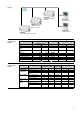
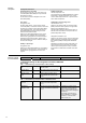
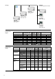
6. Chilled / heated ceiling and radiator with heating /
cooling changeover and RDG room thermostats
Partial air conditioning plant for rooms where the room temperature shall be kept constant by
a chilled / heated ceiling and a radiator.
This plant description describes a complete application with 2 rooms, covering the genera-
tion of heat or refrigeration, 2-pipe flow temperature control, chilled / heated ceilings and
radiators in the 2 rooms. The water temperature in the chilled / heated ceilings is controlled
according to the demand for heat or cooling energy from the rooms. The setpoints and ope-
rating modes are controlled from a central location.
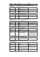
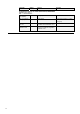
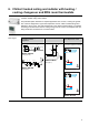
Plant diagram
Heating or refrigeration plant
Generation of heat or
refrigeration
Flow temperature control Room application
Room temperature control
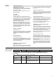
S01
S1
F3
F2
T
F1
T
B2
T
E1
M1
F10
B7
Y1
M2
F20
HB0001 H6B HQ
(basic type H4-0)
K1
M7
M4
S01
M9
M11
F7
M
Y14
T
B20
V
F18
Y7
V
F17
T
B11
CBA001 U2B HQ
(basic type C)
M4
12
S5
S01
T
B11
M
Y5
C0B001 U1B HQ
(basic type C)
RMB795B
No standard application available
TE0001 DG1 HQ
TE0001 DG1 HQ