
User Manual


45
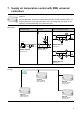
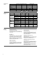
7. Supply air temperature control with RMU universal
controllers
Ventilation plant for rooms where the room temperature shall be kept constant by heating the
supply air.
This plant description describes a complete application with 2 partial ventilation plants, cov-
ering the generation of heat and its distribution to the air heating coils. The supply air tem-
perature is controlled depending on the demand for heat.
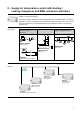
Plant diagram
Heating plant
Generation of heat
Heat distribution
Precontrol
Ventilation plants
Supply air temperature control
S01
S1
F3
F2
T
F1
T
B2
T
E1
M1
F10
B7
Y1
M2
F20
HB0001 H6B HQ
(basic type H4-0)
S01
B9
M2
F2
B7
Y1
M1
B1
S1
F1
H0F001 H6B HQ
(basic type H2-0)
1
1
S01
M3
M
Y1
M
Y2
Dp
F4
M
Y3
Dp
F1
Dp
F2
T
B1
T
B5
ADA002 U1B HQ
(basic type A)
1
1
S01
M3
M
Y1
M
Y2
Dp
F4
M
Y3
Dp
F1
Dp
F2
T
B1
T
B5
ADA002 U1B HQ
(basic type A)
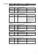
Topology
RMH760B
HB0001 H6B HQ
(basic type H4-0)
RMH760B
H0F001 H6B HQ
(basic type H2-0)
RMU710B
A
DA002 U1B HQ
(basic type A)
RMU710B
A
DA002 U1B HQ
(basic type A)