
User Manual

8
Makeup of plant descriptions
The plants contained in this document consist of individual applications a detailed de-
scription of which is given on the application sheets. This document only describes the
relevant communication settings that ensure optimum communication between the
individual devices.
The application sheets can be downloaded from Siemens’ HVAC Integrated Tool (HIT)
via the internet address given above.
Every plant description contains the same sections a brief description of which is given
below.
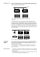
The plant diagram shows the individual sections of the plant. The applications cover-
ing the generation of heat and refrigeration are depicted at the left. At the center are
the applications covering precontrol in the form of air handling or the distribution of
water. The room applications are depicted at the right. The plant diagram consists of
applications a detailed description of which is given on the application sheets.
The topology shows at a glance the Synco devices that are used and that communi-
cate with each other. The devices are arranged according to the plant diagram, start-
ing at left with the refrigeration controller, the heating controller, then the primary con-
troller, and the room controllers or room thermostats.
The communication diagram shows the information exchanged between the devices
and the main sensors connected to the controllers. The diagram does not tell which
information is distributed in which zone.
This table gives an overview of the communication settings to be made on the control-
lers, enabling information to be exchanged as shown in the communication diagram. It
is to be noted here that if there is no need to define an outside temperature zone, it
does not automatically mean that no outside temperature is received. Certain settings
are either ready programmed or the information is distributed in some other zone (e.g.
holidays / special day zone with RDG).
This section explains the 2 aforementioned diagrams. The exchange of communica-
tion in the various communication zones is explained in detail, especially information
on what is communicated in which zones and which zone addresses are to be set.
This section shows the settings to be made on the various devices. The table only lists
the settings to be made via the Communication menu. Whether or not these settings
are visible depends on the configuration of the controller. The third column shows the
additional settings in Extra configuration, if required for opening communication.
These settings let the respective parameters appear via the Communication menu.
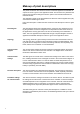
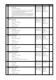
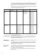
The table below gives an overview of the 8 plant descriptions. In addition to a brief
description of the different plant sections, the standard applications and Synco devices
used are listed.
Plant diagram
Topology
Communication
diagram
Communication
settings
Function description
Parameter settings
for communication