
Service manual


Chapter 5 Replacing Field-Replaceable Units 5-11
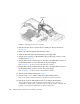
6. Push the fasteners down to lock the drive assembly into place in the chassis
(
FIGURE 5-8).
7. Redress the cable through the midwall in the chassis.
8. Route the drive data cables underneath the power supply cable.
9. Plug the power connector on the dual-drive cable to the power connector on the
motherboard (
FIGURE 5-7).
10. Plug the data connector marked J5003 on the cable to the J5003 data connector on
the motherboard (the connector furthest from the power supply).
Refer to
FIGURE 5-7 for the location of that connector.
11. Plug the data connector marked J5002 on the cable to the J5002 data connector on
the motherboard (the connector closest to the power supply).
Refer to
FIGURE 5-7 for the location of that connector.
12. Place the top cover on the chassis.
Set the cover down so that the cover hangs over the rear of the server by about an
inch (2.5 cm).
13. Slide the cover forward until it latches into place.
14. Reinstall the server in the rack and apply power to the server.
Refer to the SPARC Enterprise T1000 Server Service Manual for those instructions.
15. Label the hard drives, if necessary.
■ If you installed a single-drive 3.5-inch SATA drive assembly, then your hard drive
should already be labeled. Go to Step 16.
■ If you installed a dual-drive 2.5-inch SAS drive assembly, then you must use the
Solaris format utility to label the hard drives. Refer to the Labeling Unlabeled Hard
Drives document for those instructions.
16. Upgrade the drive controller firmware, if necessary.
If you have an older version of the drive controller firmware, then you must
upgrade the drive controller firmware to get full support for mirroring and other
RAID features.
a. Determine the version of the drive controller firmware installed on your server
by entering the following command:
# grep -i version /var/adm/messages