
Service manual


5-18 SPARC Enterprise T1000 Server Service Manual • April 2007
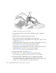
FIGURE 5-13 Installing the Dual-Drive Assembly
4. Push the fasteners down to lock the drive assembly into place in the chassis
(
FIGURE 5-13).
5. Redress the cable through the midwall in the chassis.
6. Route the drive data cables underneath the power supply cable.
7. Plug the power connector on the dual-drive cable to the power connector on the
motherboard (
FIGURE 5-11).
8. Plug the data connector marked J5003 on the cable to the J5003 data connector on
the motherboard (the connector farthest from the power supply).
Refer to
FIGURE 5-11 for the location of the J5003 data connector.
9. Plug the data connector marked J5002 on the cable to the J5002 data connector on
the motherboard (the connector closest to the power supply).
Refer to
FIGURE 5-11 for the location of the J5002 data connector.
10. Perform the procedures described in Chapter 6.
11. Use the Solaris format utility to label the 2.5-inch SAS hard drives.
Refer to the Labeling Unlabeled Hard Drives document for those instructions.
12. Perform the necessary administrative tasks to reconfigure the hard drive.
The procedures that you perform at this point depend on how your data is
configured. You might need to partition the drive, create file systems, load data from
backups, or have the data updated from a RAID configuration.
Fasteners