TC Compact Series Owner's Manual 588-682 2019-01-25 Building Technologies
Copyright Notice Copyright Notice Notice Document information is subject to change without notice by Siemens Industry, Inc. Companies, names, and various data used in examples are fictitious unless otherwise noted. No part of this document may be reproduced or transmitted in any form or by any means, electronic or mechanical, for any purpose, without the express written permission of Siemens Industry, Inc. Warning This equipment generates, uses, and can radiate radio frequency energy.
Copyright Notice To the Reader Your feedback is important to us. If you have comments about this manual, please submit them to: SBT_technical.editor.us.sbt@siemens.com Credits TALON is a registered trademark of Siemens Industry, Inc. Desigo® and Desigo® CC™ are registered trademarks of Siemens Schweiz AG. Other product or company names mentioned herein may be the trademarks of their respective owners. Printed in the USA. Siemens Industry, Inc.
Cyber security disclaimer Cyber security disclaimer Siemens provides a portfolio of products, solutions, systems and services that includes security functions that support the secure operation of plants, systems, machines and networks. In the field of Building Technologies, this includes building automation and control, fire safety, security management as well as physical security systems.
Table of Contents How to Use This Manual ............................................................................................. 9 Chapter 1—Introduction ............................................................................................ 12 TC Compact Series Product Overview.......................................................................... 12 Ordering Information ...........................................................................................
HMI and Tool Ports ............................................................................................. 32 10B/100B Ethernet Port ...................................................................................... 33 RS-485 Port ......................................................................................................... 33 USB Host Port ..................................................................................................... 33 TX-I/O Island Bus .........................
Powers Process Control Language (PPCL) Control Program and Point Database ..... 77 Control Programs ................................................................................................ 78 Point Database .................................................................................................... 78 Applications ................................................................................................................... 78 Alarm Management ............................................
How to Use This Manual How to Use This Manual About This Manual This manual is written for the owner and user of the TC Compact Series. It is designed to help you become familiar with the TC Compact and its applications. This section covers manual organization, document conventions and symbols used in the manual, how to access help, related publications, and any other information that will help you use this manual.
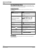
How to Use This Manual When Using TALON View Software TALON View 3.x Documentation. To view TALON View 3.x documentation, see the TALON View Online Documentation window, which you can access from the TALON View Main Menu or the TALON View program group. Document Conventions The following table lists conventions to help you use this manual in a quick and efficient manner. Convention Examples Numbered Lists (1, 2, 3…) indicate a procedure with sequential steps. 1. Turn OFF power to the field panel. 2.
How to Use This Manual Symbol Meaning Description NOTICE CAUTION Equipment damage may occur if a procedure or instruction is not followed as specified. (For online documentation, the NOTICE displays in white with a blue background.) CAUTION Minor or moderate injury may occur if a procedure or instruction is not followed as specified. WARNING Personal injury or property damage may occur if a procedure or instruction is not followed as specified.
Chapter 1—Introduction TC Compact Series Product Overview Chapter 1—Introduction Chapter 1 provides an introduction to the TC Compact Series and how it is integrated with the TALON Automation System.
Chapter 1—Introduction TC Compact Series Product Overview Ordering Information TC Compact Series Field Panels Part Number Description TC16.2-EF32.T TC Compact, 16 point, BACnet/IP ALN, FLN enabled TC16.3-UCM.T TC Unitary Equipment Controller, 16 point, BACnet MS/TP TC16.3-UCMR.T TC Unitary Equipment Controller, 16 point, BACnet MS/TP FLN, Rooftop Model TC24.2-EF32.T TC Compact, 24 point, BACnet/IP ALN or MS/TP FLN TC24.3-UCM.T TC Unitary Equipment Controller, 24 point, BACnet MS/TP TC24.3-UCMR.
Chapter 1—Introduction Compatibility with the TALON Automation System TX-I/O Power Supply and Bus Modules Product Number Description TXS1.12F4 TX-I/O Power Supply, 1.2A, 4A Fuse TXS1.EF4 TX-I/O Bus Connection Module, 4A Fuse Accessories Product Number Description TXA1.K12 One set of address keys, numbers 1-12. TXA1.K24 One set of address keys, numbers 1-24. TXA1.K-48 One set of address keys, numbers 25-48. TXA1.K-72 One set of address keys, numbers 49-72. TXA1.
Chapter 1—Introduction Compatibility with the TALON Automation System Address Assignment IP addresses are dynamically assigned by the DHCP server. If an address changes or is not recognized, the field panel firmware lets you release the dynamically assigned IP address and then reconnect the field panel to the DHCP server, accepting a new IP address assignment in the process. If there is no DHCP server at the site, you must manually assign static IP addresses as part of the startup system configuration.
Chapter 1—Introduction Principles of Field Panel Operation Principles of Field Panel Operation The TC Compact Series gathers information about the environment of your facility, as well as the equipment it monitors and controls. The TC Compact receives updated information, stores information, executes control programs, handles operator commands and requests, and makes control management decisions.
Chapter 1—Introduction Principles of Field Panel Operation ● ● Continuously executes the control program. Samples a current or voltage signal representing the room temperature and updates the value associated with that temperature in its memory. – If the temperature rises to 85°F (29°C), then the TC Compact sends an alarm message to the printer. ● Checks the current time once per second. – Between 5:00 P.M. and 7:00 A.M., the fan remains OFF. – Between 7:00 A.M. and 5:00 P.M.
Chapter 1—Introduction TALON Automation Networking How does License Manager Work? Field panels can either be ordered with licensed features and functionality pre-loaded, for example, FLN support, or upgraded to add special features, for example, TX-I/O island bus support. NOTE: The installation of some features and licenses require that the field panel be coldstarted, while others do not. Any or all of the licensed features can be activated at any time using licenses acquired from Siemens.
Chapter 1—Introduction TALON Automation Networking How Information Moves Through the Network When an operator issues a command over the ALN network through a field panel, that field panel validates the command, determines where to send it, and then passes the command to the destination over the network.
Chapter 1—Introduction TALON Automation Networking BACnet/IP Automation Level Network BACnet field panels communicate over a customer's Ethernet cabling and IP network using the ASHRAE Building Automation and Control Networking (BACnet) protocol. ● One TALON View workstation can administer up to 64 Ethernet-based BACnet/IP ALNs. ● Up to 100 BACnet/IP field panels can reside on a BACnet/IP network (1000 maximum per TALON View workstation). Figure 2: BACnet/IP ALN Network Example.
Chapter 1—Introduction TALON Automation Networking Figure 3: BACnet MS/TP ALN with MS/TP FLN Network Example. Field Level Network The TALON Field Level Network (FLN) is a data communications network that passes information between an FLN device or devices and an Automation Level Network (ALN) device, usually within one building. FLNs consist of devices that communicate using MS/TP. Siemens Industry, Inc.
0 Chapter 2—Hardware Features 16- and 24-Point Compact Series Diagram Chapter 2—Hardware Features Chapter 2 describes the TC Compact Series components and functions, as well as the enclosure used for the TC field panel series.
Chapter 2—Hardware Features 0 16- and 24-Point Compact Series Diagram TC-16 and TC-24 Features and Symbols. Terminal Block Connection 1 Label Indicates 24V ~ Supply voltage, 24 Vac input. 2 System neutral. 3 Functional earth. 4 through 12 (TC-16) 4 through 18 (TC-24) Digital Output relay. A (22 through 24) RS-485 port. +– B 10B/100B Ethernet port. C USB Device port. 25, 27, 28 Universal Input (+) (UI1 through UI3). 26, 29 – Signal Common.
0 Chapter 2—Hardware Features 36-Point Compact Series Product Diagram TC-16 and TC-24 Status LEDs. Status LED Label Indicates OFF or ON solid - No device, no connection, or bad connection. RS-485 RX (yellow) RS-485 RX Flashing - Receiving information over the RS-485 BACnet MS/TP ALN or MS/TP FLN (depending on how the port is defined). OFF or ON solid - No device, no connection, or bad connection. TC-16: DO 14 through DO 16; TC-24: DO 20 through DO 24 DO XX ON – Relay Energized.
Chapter 2—Hardware Features 36-Point Compact Series Product Diagram 0 TC-36 Features, Symbols, and Status LEDs. Terminal Block Connection Label Indicates A 10B/100B Ethernet port. B USB Device port. 30, 32, 33, 35, 36, 38 Super Universal (+). (X1 through X6) – 31, 34, 37 Signal Common. 39, 41, 50, 52, 53, 55, 56, 58, 59, 61, 62, 64, 65, 67, 68, 70, 71, 73 Universal Input/Output (+). (U7 through U24) – 40, 51, 54, 57, 60, 63, 66, 69, 72 Signal Common.
0 Chapter 2—Hardware Features Supported Point Types Supported Point Types The TC Compact Series provides software-configurable and dedicated points. The point types and their possible configurations are shown in the following tables. TC-16 Supported Point Types.
Chapter 2—Hardware Features Supported Point Types 0 TC-24 Supported Point Types. Configurable Points Universal Input (UI) Points 1-3 Point Type Universal Input/Output (U) Points 4-12 Dedicated Points Super Universal (X) Analog Output Points 13-16 (AO) Points 17-19 • • Analog Output Voltage 0 to 10 Vdc Current 0 to 20 mA • Digital Output Binary/Digital Output •4) 1) Platinum 1K 375 or 385 alpha. 2) Siemens, Johnson Controls, and DIN Standard Nickel. 3) 10K and 100K Type 2 and 10K Type 3.
0 Chapter 2—Hardware Features Compact Series Backup Batteries Compact Series Backup Batteries The TC Compact Series contains one non-rechargeable AA (LR6) battery and one non-rechargeable coin cell (BR2032) battery that serve as a power backup in the event of a power failure. The batteries only discharge during a power loss. They do not recharge. CAUTION Only use a 3.6 Volt lithium battery in TC Compact models with extended temperature range operation. Only use a 1.
Chapter 2—Hardware Features Compact Series Backup Batteries 0 Using Auto Restore and Database Backup to Flash ● ● RAM is cleared if the AA battery is dead, disabled, or missing when power to the field panel is off. In this case, if Auto Restore and Database Backup to Flash have been enabled, the database reloads in RAM when power returns; however, Trend data is lost.
0 Chapter 2—Hardware Features Memory Memory Size and Typical Battery Backup Time Memory Size and Typical Battery Backup Time.
Chapter 2—Hardware Features Memory 0 – When auto-restore is enabled, a coldstart does not result in the same downtime as with earlier revisions of TALON firmware. Because there is no waiting on a full download from the backup system, the database is restored from flash so quickly that there is little to no downtime. However, the accumulated trend data is deleted from memory. – Database restoration from flash is disabled by default.
0 Chapter 2—Hardware Features Communication Connections Random Access Memory (RAM) Synchronous Dynamic Random Access Memory (SDRAM) is the working memory of the TC Compact. When the TC Compact has booted and is operating normally, the TALON firmware, the PPCL control program, the point database, and trend data have been transferred from Flash ROM.
Chapter 2—Hardware Features 0 Communication Connections USB Device Port The USB Device port supports a generic serial interface for an HMI or Tool device. The USB Device port does not support firmware flash upgrades. 10B/100B Ethernet Port The 10B/100B Ethernet port provides a path for commands and information transmitted between field panels inside a firewall. This port provides both full- and halfduplex 10Base-T or 100Base-TX compliant communications over a BACnet/IP Automation Level Network (ALN).
0 Chapter 2—Hardware Features HOA (Hand-Off-Auto) Upgrade Kits TX-I/O Island Bus The TC-36 offers the flexibility of expanding the total point count through a self-forming island bus. With the addition of TX-I/O modules and a TX-I/O Power Supply, up to 16 points (or four TX-I/O modules) can be supported. An additional license may be required to enable the Island Bus.
Chapter 2—Hardware Features HOA (Hand-Off-Auto) Upgrade Kits 0 Users can override the default switch assignment or customize the switches to their desired configuration. ● The HOA module can be used to override outputs and monitor inputs. ● The HOA mapping and definition of a logical point in the database can be done in any order. ● The HOA is hot-swappable. The module can be installed without powering down the controller and interrupting facility operations.
0 Chapter 2—Hardware Features HOA (Hand-Off-Auto) Upgrade Kits Using the HOA Switches LED and Override Status Placing Device into Override To manually override the present value of an analog or digital output on the TC Compact, you must engage the appropriate switch assigned to the desired equipment to be controlled. Pressing the center of the switch enables the Override mode and energizes the Yellow Override status LED.
Chapter 2—Hardware Features HOA (Hand-Off-Auto) Upgrade Kits 0 Manual Control Settings for Analog Outputs 7 70% 7 15.2 8 80% 8 16.8 9 90% 9 18.4 10 100% 10 20 Digital Output Override Pressing the switch causes the output to turn ON and the Green I/O status LED is ON at 100%. Pressing the switch causes the output to turn OFF and the Green I/O status LED is OFF at 0%. The Yellow Override status LED will flash momentarily for any change in value.
0 Chapter 2—Hardware Features HOA (Hand-Off-Auto) Upgrade Kits Default Mapping For each type of TC Compact (16, 24 and 36) that supports HOA and each HOA unit (8, 16 rooftop or 16 non-rooftop UL 864), there is a default mapping between each button and physical point. The default mapping provides Plug-and-Play functionality.
Chapter 2—Hardware Features 0 HOA (Hand-Off-Auto) Upgrade Kits PXM10S/T Product Overview and Description NOTE: All figures show the BACnet version of the PXM10S and PXM10T. The appearance of the proprietary version may differ slightly. PXM10S and PXM10T are optional controller mounted Operator Display modules that provide a password protected user interface. This interface allows you to interact with the existing field panel database and its immediate sub-networked Siemens (FLN) devices.
0 Chapter 2—Hardware Features HOA (Hand-Off-Auto) Upgrade Kits ● ● ● ● ● ● INFO button provides one touch access to detailed system information for points. Manual and automatic login option for enhanced security or easy access. View point information and status, view and acknowledge alarms, and command/release local field panel points. Point Monitor – Can customize a group of points to continuously display and refresh with updated values (PXM10S only).
Chapter 2—Hardware Features 0 HOA (Hand-Off-Auto) Upgrade Kits NOTE: You must have sufficient operator access permissions to the Alarms, Points, and Point Monitor applications to fully use all features and corresponding submenus. Operator Display Layout Display screen – Displays splash screen with either PXM10S or PXM10T module, device Firmware Revision, field panel Firmware Revision number, and Cimetrics BACstac revision number.
0 Chapter 2—Hardware Features HOA (Hand-Off-Auto) Upgrade Kits ESC button – Press once to return to previous menu/page or backspace during text/value editing. INFO button – Press once to navigate to the window containing all available information about the point on selected line. Alarm Window There are two ways to view alarms, both of which display the alarm list with the point system name and status: ● Alarm button. Provides direct access to the list of unacknowledged alarms. ● Alarm menu.
Chapter 2—Hardware Features HOA (Hand-Off-Auto) Upgrade Kits 0 Operator Display Menu Tree Siemens Industry, Inc.
0 Chapter 2—Hardware Features HOA (Hand-Off-Auto) Upgrade Kits Main Menu Structure All menu screen captures in this manual reflect the PXM10S module. Not all menu options/features shown are available with the PXM10T module. NOTE: A solid DOWN arrow in the top right corner of the display screen indicates more menu options are available and a solid UP arrow indicates more items are available after the last highlighted item.
Chapter 2—Hardware Features 0 HOA (Hand-Off-Auto) Upgrade Kits NOTE: Default user account login information for PXM10S or PXM10T is on a per ALN account basis. If your network contains an assortment of field panels with Firmware Revisions earlier than 3.2.2, the AutoLogin account is not replicated or passed onto other field panels. For more information about workstation user accounts, see the TALON ViewOnline Help system.
0 Chapter 2—Hardware Features HOA (Hand-Off-Auto) Upgrade Kits Language ID PPCL N (No_access) R (Read_only) C (Command) E (Edit) (default setting) FLN devices N (No_access) R (Read_only) C (Command) E (Edit) (default setting) Equipment Scheduler N (No_access) R (Read_only) C (Command) E (Edit) (default setting) System N (No_access) R (Read_only) C (Command) E (Edit) (default setting) Diagnostics N (No_access) R (Read_only) C (Command) E (Edit) (default setting) Users N (No_access) R (Read_only
Chapter 2—Hardware Features 0 HOA (Hand-Off-Auto) Upgrade Kits Example >User initials : tiny >Account name : PXM10TINY---------------------->Password : ?????--------->Verify password : ?????--------->System, User namespace : U >Access group(s) : 1..
0 Chapter 2—Hardware Features HOA (Hand-Off-Auto) Upgrade Kits Menu/Submenu Step Splash screen/logo Press the dial. Login Description Rotate the dial to highlight Automatic Login. Login menu displays. Press the dial to select Automatic Login. System logs you into the Main menu of the module. Figure 8: Main Menu Manual Login Do the following to manually log in to the PXM10S or PXM10T module. The default language for manual login is U.S. English.
Chapter 2—Hardware Features HOA (Hand-Off-Auto) Upgrade Kits Menu/Submenu Step 0 Description Press the dial twice to move to the PWD fields. For PWD, rotate the dial highlight each character. Press the dial to select a character. Repeat until you enter the complete password. NOTE: If you need to return to the previous editable field, for example from PWD fields back to USR fields, press ESC. To proceed to the next field, press the dial. Press the dial to confirm USR and PWD.
0 Chapter 2—Hardware Features HOA (Hand-Off-Auto) Upgrade Kits Menu/Submenu Step Description Main Rotate DIAL to highlight Logoff. Press DIAL/OK to and select Logoff. Confirm Logoff Are you sure? Displays the Logoff submenu. Rotate DIAL to highlight Yes or No. Press DIAL/OK to make selection. Confirms logoff and returns to splash screen. NOTE: If you press ESC, you are prompted with the same Confirm Logoff screen.
Chapter 2—Hardware Features 0 HOA (Hand-Off-Auto) Upgrade Kits Menu/Submenu Step Description Rotate DIAL to highlight the last point (bottom of screen), and then rotate DIAL once more. Refreshes the screen and displays the previous screens last highlighted point, as well as the next series of points. Repeat steps until you reach the end of the point list.
0 Chapter 2—Hardware Features HOA (Hand-Off-Auto) Upgrade Kits Commanding Points Do the following to change the point value and command the points in the field panel. These steps also apply to commanding TEC subpoints. Figure 14: Point Action Command Submenu Menu/Submenu Step Description Main Rotate DIAL to highlight Points. Press DIAL/OK to select Points. Displays the Points menu. Points Press DIAL/OK to highlight desired point. Displays the Point Action Command submenu.
Chapter 2—Hardware Features HOA (Hand-Off-Auto) Upgrade Kits 0 Figure 16: Edit Command Point Value Submenu Releasing Points Do the following to change a point priority and release a point. Figure 17: Point Action Release Priority Submenu Menu/Submenu Step Description Main Rotate DIAL to highlight Points. Press DIAL/OK to select Points. Points Displays the Points menu. Rotate DIAL to highlight desired point. Press DIAL/OK to select point.
0 Chapter 2—Hardware Features HOA (Hand-Off-Auto) Upgrade Kits Menu/Submenu Step P2 Point Action: Rotate DIAL to highlight Release Priority. Description Press DIAL/OK to select Release Priority. Rotate DIAL to select Yes or No. Press DIAL/OK. This releases the priority to NONE. Press ESC. Returns you to the previous menu without changing the point priority.
Chapter 2—Hardware Features HOA (Hand-Off-Auto) Upgrade Kits Menu/Submenu Step Main Rotate DIAL to highlight Point Monitor. Point Monitor 0 Description Press DIAL/OK to select Point Monitor. Displays the Point Monitor menu. Rotate DIAL to highlight Configure. Displays all available points at the field panel. Press DIAL/OK to select Configure. Edit Pt Monitor Rotate DIAL to highlight desired point. Displays black background, allowing you to edit field. Press DIAL/OK to select point.
0 Chapter 2—Hardware Features HOA (Hand-Off-Auto) Upgrade Kits Menu/Submenu Step Description Edit Pt Monitor Rotate DIAL to select desired point. Displays all available points and subpoints at the field panel. Subpoints Rotate DIAL to select subpoint. Displays a list of subpoints associated with the selected point. Press DIAL/OK to select Y or N. Y=Yes; point is monitored. N=No; point is not monitored. (This is the default setting.) Press ESC. Returns you to the Point Monitor menu.
Chapter 2—Hardware Features HOA (Hand-Off-Auto) Upgrade Kits 0 Displaying Monitored Points Automatic logoff occurs after a predetermined amount of inactivity, however: ● The Point Monitor continues to display points and refreshes the Display screen every four seconds. ● You can scroll the Point Monitor, but the function keys (INFO, ESC, Alarm) are disabled. ● If you press any of the key functions, the login splash screen prompts you to login. Do the following to display monitored points.
0 Chapter 2—Hardware Features HOA (Hand-Off-Auto) Upgrade Kits Figure 26: Adjust Brightness Submenu Menu/Submenu Step Main Rotate DIAL to highlight Settings. Description Press DIAL/OK to select. Settings Displays the Settings menu. Press DIAL/OK to highlight Brightness. Press DIAL/OK to select Brightness. Brightness Displays the Brightness submenu. Rotate DIAL to highlight Adjust Brightness. Press DIAL/OK to select Adjust Brightness. Rotate DIAL to select a value.
Chapter 2—Hardware Features HOA (Hand-Off-Auto) Upgrade Kits Menu/Submenu Step Main Rotate DIAL to highlight Settings. 0 Description Press DIAL/OK to select. Displays the Settings menu. Settings Press DIAL/OK to highlight and Displays the Color submenu. select Color. Color Rotate DIAL to highlights and select Adjust Color. Rotate DIAL to toggle between Displays the backlight color you choose. Blue and White color. Press DIAL/OK to select. Applies the value and returns you to the previous menu.
0 Chapter 2—Hardware Features HOA (Hand-Off-Auto) Upgrade Kits Menu/Submenu Step Timeout Rotate DIAL to highlight and select Adjust Timeout. Description Rotate DIAL to select a value. Valid Timeout values are 0 through 240 seconds. Press DIAL/OK to select. Applies the value and returns you to the previous menu. Press ESC. Returns you to the Settings menu without applying the new value.
Chapter 2—Hardware Features HOA (Hand-Off-Auto) Upgrade Kits 0 FLN Node Mode When the UEC is operating in FLNnode mode, it has the capability to monitor points from other devices, and recognize the point by device specific name, or BACnet encoded name. However a point log display should show only points that reside locally on the UEC. Some functions, depending on the exchange of proprietary messages, such as replication, and database download, are not available.
0 Chapter 2—Hardware Features HOA (Hand-Off-Auto) Upgrade Kits Unitary Equipment Controller Specifications Dimensions (L × W × D) TC Unitary Equipment Controller, 16 point, BACnet MS/TP 10.7" × 5.9" × 2.45" (272 mm × 150 mm × 62 mm) TC Unitary Equipment Controller, 24 point, BACnet MS/TP 10.7" × 5.9" × 2.45" (272 mm × 150 mm × 62 mm) 1.38" × 0.30" × 0.04" (35 mm × 7.5 mm × 1 mm) DIN rail (EN 60715 TH 35-7.
Chapter 2—Hardware Features HOA (Hand-Off-Auto) Upgrade Kits 0 Electrical Digital Output Class 1 Relay Analog Output 0 to 10 Vdc Universal Input (UI) and Universal Input/Output (U) Analog Input Voltage (0-10 Vdc) Current (4-20 mA) 1K Ni RTD @ 32°F 1K Pt RTD (375 or 385 alpha) @ 32°F 10K NTC Type 2 or Type 3 Thermistor @ 77°F 100K NTC Type 2 Thermistor @ 77°F Digital Input Pulse Accumulator Contact Closure Sensing Dry Contact/Potential Free inputs only Supports counter inputs up to 20 Hz Analog Output
0 Chapter 2—Hardware Features TX-I/O Product Range Overview Agency Listings UL916 PAZX (all models) UL916 PAZX7 (all models) UL Agency Compliance FCC Compliance CFR47 Part 15, Subpart B, Class B Australian EMC Framework European EMC Directive (CE) European Low Voltage Directive (LVD)BACnet Testing Laboratories (BTL) Certified, Firmware Revision 3.
Chapter 2—Hardware Features 0 TX-I/O Product Range Overview The design of the TX-I/O Modules provides optimum diagnostics and results in a more efficient installation and maintenance workflow. ● Field wiring may be terminated prior to installation of electronics. ● Connected peripheral devices can be measured without affecting or being affected by the I/O module.
0 Chapter 2—Hardware Features TX-I/O Product Range Overview TX-I/O Module Symbols and Status LEDs LED, Symbol, or Feature The picture can't be displayed. 7 Override status LEDs (yellow) LED or Symbol Indication - Output (arrow pointing OUT from center of module). - Input (arrow pointing IN toward center module). - 24 Vdc output (field supply). - 24 Vac output (field supply). ON Manual operation; a local override is active. OFF No voltage or manual operation off.
Chapter 2—Hardware Features 0 TX-I/O Product Range Overview TX-I/O Module LCD Panel for Errors and Reminders (Displays in LCD Top Row) Inactive point Invalid value No voltage Unconfigured point TX-I/O LCD Panel by Point Type.
0 Chapter 2—Hardware Features TX-I/O Product Range Overview The keys are available in sets of 24, up to a maximum value of 72 (two sets of 12, 124, 25-48, and 49-72). ● The I/O module address is mechanically encoded in the address key. – Without an address key, the module is inactive. – With an address key inserted, the module has full functionality.
Chapter 2—Hardware Features TX-I/O Product Range Overview 0 TX-I/O Power Supply Overview The TX-I/O Power Supply bridges communication and power from one DIN rail to another and generates 28.8 W (1.2A at 24 Vdc) to power TX-I/O modules and peripheral devices. ● An LED provides an indication of 24 Vdc on the TX-I/O bus. ● Up to 4 TX-I/O Power Supplies can be operated in parallel, with a maximum of two per DIN rail. ● It can be located within a row of TX-I/O modules or at the beginning of a new DIN rail.
0 Chapter 2—Hardware Features PX Series Enclosures and Service Boxes PX Series Enclosures and Service Boxes PX Series enclosures house both electronic and pneumatic components. The enclosures include a perforated backplane for mounting TC Series field panels or other electronic or pneumatic components. General features of the enclosures include: ● Availability in three sizes to match installation needs: 18-, 19-, and 34-inch.
Chapter 2—Hardware Features PX Series Enclosures and Service Boxes 0 Figure 33: PX Series Service Box (115V), 34-inch enclosure. Figure 34: PX Series Service Box (115V), 19-inch enclosure. Siemens Industry, Inc.
0 Chapter 2—Hardware Features PX Series Enclosures and Service Boxes Figure 35: PX Series Service Box Connectors. ● ● Each Service Box distributes the total 24 Vac power provided to the plug-in terminations on the left side. – Two Class 1 power-limited terminations distribute up to the total power to controllers and power supplies inside the same enclosure. – Earth ground is provided on the CTLR termination.
Chapter 2—Hardware Features PX Series Enclosures and Service Boxes 0 PX Series Enclosure Specifications PX Series 18" Enclosure Specifications Dimensions (H × W × D) 18" × 14" × 6" (457.2 mm × 355.6 mm × 152.
0 Chapter 2—Hardware Features PX Series Enclosures and Service Boxes PX Series Service Box Specifications Power Requirements for 115 Vac Service Boxes PXA-SB115V192VA Input: 115 Vac +/- 15%, 50/60 Hz +/- 5%, 220VA maximum, 2A CB Output: 24 Vac +/- 20%, 50/60 Hz +/- 5%, 192VA maximum PXA-SB115V384VA Input: 115 Vac +/- 15%, 50/60 Hz +/- 5%, 440VA maximum, 4A CB Output: 24 Vac +/- 20%, 50/60 Hz +/- 5%, 384VA maximum 115 Vac models also have a duplex outlet, which is protected by Mains 20A or 15A CB for use
Chapter 2—Hardware Features PX Series Enclosures and Service Boxes ● ● ● Siemens Industry, Inc. Building Technologies 0 Space between door panel and opening obstruction must be at least 11 inches (279.4 mm) to allow for door removal at 40 degrees, or 28 inches (711 mm) with a cabinet mounting at least 19 inches (483 mm) from the left side wall to allow door to completely open at 135 degrees. 5 inches (127 mm) minimum horizontal distance between the enclosure and any obstruction to the left and right.
Chapter 3—Applications Operator Interface Chapter 3—Applications Chapter 3 describes the program and applications provided with or available for the TC Compact Series.
Chapter 3—Applications Powers Process Control Language (PPCL) Control Program and Point Database Network Layout ● ● ● View network layout Navigate to other Web-enabled panels Search database for individual points System Status Bar ● ● ● Visual indication of new alarms and unacknowledged alarms Visual indication of out of service, faults, and failed devices Ability to view, filter, and acknowledge system alarms from a single page Point Commanding ● ● ● Change point values Place points “Out of Service
Chapter 3—Applications Applications Control Programs The control programs define all user-defined control logic, calculations, applications, and so on for the TC Compact. PPCL is written in an English-based programming language called Powers Process Control Language (PPCL). It is a powerful programming language developed specifically for controlling Heating, Ventilating, and Air Conditioning (HVAC) equipment.
Chapter 3—Applications Applications Alarm Management An alarm is a status that indicates whether a point value or state is above or below a defined value. Alarm management is the strategy used to define, route, acknowledge, and resolve those alarms. Points are defined as alarmable for the following reasons: ● To prevent critical problems. Points that affect human safety or can cause a severe problem in building operation should be defined as alarmable.
Chapter 3—Applications Customized Applications Specifically, a system administrator can perform the following tasks: ● ● ● Define the users that can access an ALN Assign access to access groups Assign privileges to field panel functions residing on an ALN Controlling User Access to Field Panel Functions The following four access levels can be assigned to any field panel function for any user. ● No Access – Users cannot see the function. ● Read Only – Users can only view the value or status of objects.
Chapter 3—Applications SNMP Three versions of SNMP exist: SNMP version 1 (SNMPv1), SNMP version 2 (SNMPv2), and SNMP version 3 (SNMPv3). All three versions have a number of features in common, but SNMPv2 offers enhancements such as additional protocol operations. SNMPv3 offers additional enhancements to Internet security and communities. SNMP users UDP ports 161 and 162, which must be opened within the firewall settings. The panel may coldstart after the SNMP license is loaded.
Chapter 4—Troubleshooting Service Information Chapter 4—Troubleshooting NOTE: The following information is for qualified service personnel only. Chapter 4 describes corrective measures you can take if you encounter a problem with a TC Compact Series controller. If you encounter a symptom or a problem not covered in this manual, contact your Siemens Solution Partner, Authorized TALON Dealer.
Chapter 4—Troubleshooting Service Information Electrostatic Discharge An electrostatic discharge (ESD) wrist strap is generally not required when installing or servicing a TC Compact. However, if the field panel is installed in a very dry environment where a high static discharge is likely, an ESD wrist strap is recommended. Error Status Messages For error status message descriptions, see the TALON Firmware User's Manual (588580) (588-580).
Chapter 4—Troubleshooting Troubleshooting Compact Field Panels Reinstalling the Mounting Tabs Do the following to reinstall a DIN mounting tab: 1. Place the wire spring clip into the pocket in the channel for the mounting tab. 2. Make sure the mounting tab is face down. 3. Working from the center (inside) of the base, slide the mounting tab into the channel. (See the following figure.) NOTE: The end with the screw hole slides into the channel first. Figure 37: Reinstalling a DIN Mounting Tab.
Chapter 4—Troubleshooting Troubleshooting Compact Field Panels 3. Check that the battery is properly seated in the battery holder. 4. Replace the battery. BATT LOW LED remains on after the battery has been replaced. Verify that the correct type of battery is being used. The LOW BATT LED remains ON if an alkaline battery is used in TC Compact models with extended temperature range operation. CAUTION Only use a 3.6 Volt lithium battery in TC Compact models with extended temperature range operation.
Chapter 4—Troubleshooting Troubleshooting the TX-I/O Island Bus Communication Points cannot be read or commanded from the operator's terminal. 1. Verify that failed points have been properly addressed. 2. Verify the status of the points at the operator's terminal. Verify that points are not under Operator priority. No communication over the FLN trunk. 1. Verify the FLN address and communication speed. 2. Verify the FLN trunk is connected to the correct FLN port.
Chapter 4—Troubleshooting Troubleshooting the TX-I/O Island Bus CAUTION The TX-I/O™ island bus must extend from the male bus connector of the TX-I/O Power Supply or Bus Connection Module. • The TX-I/O Power Supply and Bus Connection Module only supply 24 Vac to I/O modules on the male bus connector. • I/O modules on the female bus connector of the TX-I/O Power Supply or Bus Connection Module do not receive power and have a fault condition.
Glossary Glossary The glossary contains terms and acronyms that are used in this manual. 1 100Base-TX: Fast Ethernet network implementation. 100Base-TX stands for 10Mbps baseband twisted-pair cable. The “X” stands for 100Base-X, the IEEE identifier for the media system used by 100Base-TX. 10Base-T: Ethernet network implementation. 10Base-T stands for 10Mbps baseband twisted-pair cable. A alarm priority: Ranking of a point alarm.
Glossary Domain Name Server (DNS): Common method of assigning computer names in UNIXbased networks. A DNS server maintains a list of host names and IP addresses, allowing computers that query them to find remote computers by specifying host names rather than IP addresses. DNS is a distributed database; therefore, DNS servers can be configured to use a sequence of name servers, based on the domain in the name being looked for.
Glossary P Plain Old Telephone Service (POTS): Acronym for the standard telephone service that is used in most homes. Communication speed is generally restricted to 52K bps. point condition: State of a point such as normal, alarm, alarm-by-command, failed, operator disabled, or proofing. R Read Only Memory (ROM): Non-volatile, permanent, but field-programmable memory that stores the operating system of the field panel.
Index Index 1 10B/100B Ethernet port........................................... 33 16- and 24-point Compact product diagram ................................................... 23 status LEDs .......................................................... 23 16-point Compact supported point types ........................................... 26 2 24-point Compact supported point types ........................................... 26 3 36-point Compact product diagram ............................................
Index L loop/loop tuning ...................................................... 79 M Management Level Network (MLN) ......................... 18 memory compressed ROM................................................. 30 Flash Read-Only Memory (ROM)......................... 30 memory size and battery backup time.................. 30 Random Access Memory (RAM) .......................... 32 O operator interface ................................................... 76 P power supply module ................
Issued by Siemens Industry, Inc. Building Technologies Division 1000 Deerfield Pkwy Buffalo Grove IL 60089 +1 847-215-1000 Document ID: 588-682 Edition: 2019-01-25 © Siemens Industry, Inc., 2019 Technical specifications and availability subject to change without notice.