Technical Bulletin Document No. 155-253P25 TB 239 December 9, 2003 Powers™ Controls Calibration Kit for Room and Duct Thermostats Product Number 832-177 Caution Notation CAUTION: Description This kit contains the equipment required to test pneumatic room and duct thermostats and pneumatic devices such as valve or damper actuators or positioning relays. Table 1 lists the items contained in the calibration kit. Equipment damage or loss of data may occur if you do not follow procedures as specified.
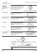
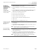
Technical Bulletin Document Number 155-253P25 December 9, 2003 Description, Continued Dual Scale Pressure Gauge Calibration Kit for Room and Duct Thermostats The dual scale pressure gauge has a dual scale of 0 to 30 psi and 0 to 200 kPa, and is bottom-connected. It is used to measure the air pressure being delivered to a pneumatic device or the branch line pressure of a thermostat. Figure 3. Dual Scale Pressure Gauge.
Calibration Kit for Room and Duct Thermostats Calibration Instructions TH-180D and TH-180R Single Temperature Room Thermostats Required Tools Thermometer Calibration Technical Bulletin Document Number 155-253P25 December 9, 2003 Table of Contents TH-180D and TH-180R Single Temperature Room Thermostats............................... 3 TH-182 HC Heating- Cooling Thermostat ...................................................................
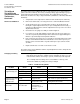
Technical Bulletin Document Number 155-253P25 December 9, 2003 Calibration Kit for Room and Duct Thermostats TH-180D and TH-180R Single Temperature Room Thermostats, Continued The thermostat is factory-calibrated to pass a control pressure of 7 to 8 psi at 72.5°F (48.2 to 55.1 kPa at 22.5°C). The factory sensitivity setting is approximately 2.5 psi per degree Fahrenheit (31.0 kPa per degree Celsius). The supply air pressure to the thermostat should be 18 to 25 psi, 30 psi maximum (124.0 kPa to 172.
Calibration Kit for Room and Duct Thermostats TH-180D and TH-180R Single Temperature Room Thermostats, Continued Troubleshooting Control pressure remains at 1/2 psi (3.4 kPa) Technical Bulletin Document Number 155-253P25 December 9, 2003 1. Remove the thermostat cover and connect the pressure gauge assembly. See Thermostat Calibration, Steps 1 through 4. 2. Check the throttling pin to see if it is in place under the center leg of the bi-metal element. 3.
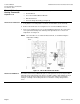
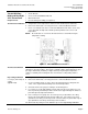
Technical Bulletin Document Number 155-253P25 December 9, 2003 TH-182 HC HeatingCooling Thermostat Required Tools Calibration Kit for Room and Duct Thermostats • Small, flat-blade screwdriver (not included) • Nozzle Wrench • Cover Screw and Calibration Wrench • Dial Thermometer • Pressure Gauge Assembly (see Figure 9) Thermometer Calibration 1. Verify that the room temperature is between 70°F and 80°F (21°C and 27°C). 2. Remove the thermostat cover using the Cover screw and calibration wrench.
Calibration Kit for Room and Duct Thermostats Technical Bulletin Document Number 155-253P25 December 9, 2003 TH-182 HC Heating- 1. Verify that room temperature is between 70°F to 80°F (21.1°C to 26.7°C). Cooling Thermostat, 2. Remove the thermostat cover using the Cover screw and calibration wrench. Continued 3. Use the Cover screw and calibration wrench to set the cooling dial to room temperature by inserting it into the center of the setpoint dial and turning to the desired temperature.
Technical Bulletin Document Number 155-253P25 December 9, 2003 TH-182 HC HeatingCooling Thermostat, Continued Calibration Kit for Room and Duct Thermostats There are three types of malfunction that might occur, and these can be corrected as follows. Before beginning: • Ensure that there is 18 psi or 25 psi (124.0 kPa and 172.2 kPa) of clean, dry air supply.
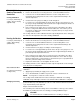
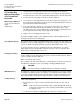
Calibration Kit for Room and Duct Thermostats TH-182DN and TH-182 DNV DayNight and Day-Night Vent Thermostats Required Tools Technical Bulletin Document Number 155-253P25 December 9, 2003 • Small, flat-blade screwdriver (not included) • Nozzle Wrench • Cover Screw and Calibration Wrench • Dial Thermometer • Pressure Gauge Assembly (see Figure 9) Thermometer Calibration 1. Verify that the room temperature is between 70°F and 80°F (21°C and 27°C). 2.
Technical Bulletin Document Number 155-253P25 December 9, 2003 Calibration Kit for Room and Duct Thermostats TH-182DN and TH-182 DNV DayNight and Day-Night Vent Thermostats, Continued 1. Verify that the room temperature is between 70°F and 80°F (21°C and 27°C). Night Setting Calibration 4. Loosen the test screw approximately 1/2 turn. Place the pressure gauge hose over the test port body. Stand away from the thermostat for approximately five minutes to prevent body heat temperature influence.
Calibration Kit for Room and Duct Thermostats Technical Bulletin Document Number 155-253P25 December 9, 2003 TH-182DN and 1. Use either 18 psi (day) or 25 psi (night) (124.0 or 172.2 kPa) air supply. TH-182 DNV DayNight and Day-Night 2. Remove the thermostat cover and connect the pressure gauge. See Thermostat Calibration, Steps 1 through 4. Vent Thermostats, Continued 3. Check the throttling pin to see if it is in place under the center leg of the bi-metal If control pressure remains at 1/2 psi (3.
Technical Bulletin Document Number 155-253P25 December 9, 2003 Direct Acting D Room Thermostat Required Tools Calibration Calibration Kit for Room and Duct Thermostats • D Adjustment Key • Small, flat-blade screwdriver (not included) • Dial Thermometer • Pressure Gauge Assembly (see Figure 9) 1. Verify that the room temperature is between 70°F and 80°F (21°C and 27°C). 2. Remove thermostat cover using D Adjustment Key. 3. Construct Pressure gauge assembly as shown in Figure 9. 4.
Calibration Kit for Room and Duct Thermostats Technical Bulletin Document Number 155-253P25 December 9, 2003 D Day-Night Thermostats • D Adjustment Key • Small, flat-blade screwdriver (not included) Required Tools • Dial Thermometer • Pressure Gauge Assembly (see Figure 9) Calibration Day Setting 1. Verify that the room temperature is between 70°F and 80°F (21°C and 27°C). 2. Remove the thermostat cover using the D Adjustment Key. 3. Verify that the supply pressure is 18 psi (124 kPa) pressure.
Technical Bulletin Document Number 155-253P25 December 9, 2003 Calibration Kit for Room and Duct Thermostats D Day-Night Thermostats, Continued 1. Verify that the room temperature is between 70°F and 80°F (21°C and 27°C). Night Setting 3. Repeat Day Setting Steps 4 through 11 to calibrate the night (right) scale. 2. Verify that the supply pressure is 25 psi (172 kPa). 4. Replace the thermostat cover and tighten the two screws. Manual Reset - System 1.
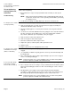
Calibration Kit for Room and Duct Thermostats Technical Bulletin Document Number 155-253P25 December 9, 2003 TH-192 S Single Temperature Room Thermostat • Small, flat-blade screwdriver (not included) • Needle nose pliers • Cover Screw and Calibration Wrench Required Tools • Dial Thermometer • Dual Scale Pressure Gauge and Pressure Tap Needle (assembled) Thermometer Calibration 1. Verify that the room temperature is between 70°F and 80°F (21°C and 27°C). 2.
Technical Bulletin Document Number 155-253P25 December 9, 2003 Calibration Kit for Room and Duct Thermostats Limit Stop Adjustment, Continued 5. Repeat with second limit stop tab. NOTE: Changing the limit stop position one gear tooth changes the limit stop setting by 1-1/3°F (0.7°C). Thermostat Calibration The thermostat is factory calibrated to a control pressure of 7.5 psi (52 kPa) when the setpoint and the ambient temperature are both at 72°F (22°C).
Calibration Kit for Room and Duct Thermostats TH192 HC Heating/ Cooling Room Thermostat Required Tools Thermometer Calibration Technical Bulletin Document Number 155-253P25 December 9, 2003 • Small, flat-blade screwdriver (not included) • Needle nose pliers • Dial Thermometer • Cover Screw and Calibration Wrench • Dual Scale Pressure Gauge and Pressure Tap Needle, assembled 1. Verify that the room temperature is between 70°F and 80°F (21°C and 27°C). 2.
Technical Bulletin Document Number 155-253P25 December 9, 2003 TH192 HC Heating/ Cooling Room Thermostat Sensitivity Adjustment Calibration Kit for Room and Duct Thermostats The factory thermostat sensitivity setting is approximately 2.5 psi/°F (31 kPa/°C).
Calibration Kit for Room and Duct Thermostats TH192 HC Heating/ Cooling Room Thermostat, Continued Cooling Calibration Technical Bulletin Document Number 155-253P25 December 9, 2003 1. Verify that the room temperature is between 70°F and 80°F (21°C and 27°C). 2. If not already done, remove the cover using the Cover screw and calibration wrench. 3. Verify that the supply pressure is 18 psi (124 kPa). Set the cooling dial to the room temperature by turning the exposed adjustment knob.
Technical Bulletin Document Number 155-253P25 December 9, 2003 TH192 DN Day/Night and DNV Room Thermostat Required Tools Thermometer Calibration Calibration Kit for Room and Duct Thermostats • Small, flat-blade screwdriver (not included) • Needle nose pliers • Cover Screw and Calibration Wrench • Dial Thermometer • Dual Scale Pressure Gauge and Pressure Tap Needle, assembled 1. Verify that the room temperature is between 70°F and 80°F (21°C and 27°C). 2.
Calibration Kit for Room and Duct Thermostats Technical Bulletin Document Number 155-253P25 December 9, 2003 TH192 DN Day/Night The factory thermostat sensitivity setting is approximately 2.5 psi/°F (31 kPa/°C).
Technical Bulletin Document Number 155-253P25 December 9, 2003 TH192 DN Day/Night and DNV Room Thermostat, Continued Day Setting Calibration Calibration Kit for Room and Duct Thermostats 1. Verify that the room temperature is between 70°F and 80°F (21°C and 27°C). 2. Remove the cover using the Cover screw and calibration wrench. 3. Verify that the supply pressure is 18 psi to 25 psi (124 kPa to 72 kPa). Set the day (right) dial to the room temperature by turning the exposed adjustment knob.
Calibration Kit for Room and Duct Thermostats Technical Bulletin Document Number 155-253P25 December 9, 2003 Free Energy Band™ TH193 HC Heating/Cooling Room Thermostat • Small, flat-blade screwdriver (not included) • Needle nose pliers • Cover Screw and Calibration Wrench Required Tools • Dial Thermometer • Dual Scale Pressure Gauge and Pressure Tap Needle, assembled Thermometer Calibration 1. Verify that the room temperature is between 70°F and 80°F (21°C and 27°C). 2.
Technical Bulletin Document Number 155-253P25 December 9, 2003 Free Energy Band™ TH193 HC Heating/Cooling Room Thermostat, Continued Limit Stop Adjustment Calibration Kit for Room and Duct Thermostats Thermostat limit stops define the minimum and maximum thermostat setpoints. The limit stops engage in the setpoint cam gear teeth and cause interference between the set point cam gear and the adjustment knob gear. To change the limit stop settings: 1.
Calibration Kit for Room and Duct Thermostats Technical Bulletin Document Number 155-253P25 December 9, 2003 Free Energy Band™ 1. Verify that the room temperature is between 70°F and 80°F (21°C and 27°C). TH193 HC 2. Remove the cover using the Cover screw and calibration wrench. Heating/Cooling Room Thermostat, 3. Verify that the supply pressure is 18 psi to 25 psi (124 kPa to 172 kPa).
Technical Bulletin Document Number 155-253P25 December 9, 2003 Free Energy Band™ TH193 HC Heating/Cooling Room Thermostat, Continued Troubleshooting Calibration Kit for Room and Duct Thermostats Before troubleshooting the thermostat per Table 2, make certain there is clean dry supply air at 18 psi (cooling) or 25 psi (heating) (124 or 172 kPa). Use the Dual Scale Pressure Gauge and Pressure Tap Needle to measure the control pressure at the output test port (see Figure 18).
Calibration Kit for Room and Duct Thermostats Technical Bulletin Document Number 155-253P25 December 9, 2003 Free Energy Band™ TH193 HC Hesitation Room Thermostat, • Small, flat-blade screwdriver (not included) • Needle nose pliers • Cover Screw and Calibration Wrench Required Tools • Dial Thermometer • Dual Scale Pressure Gauge and Pressure Tap Needle, assembled Thermometer Calibration 1. Verify that the room temperature is between 70°F and 80°F (21°C and 27°C). 2.
Technical Bulletin Document Number 155-253P25 December 9, 2003 Free Energy Band™ TH193 HC Hesitation Room Thermostat, Continued Limit Stop Adjustment Calibration Kit for Room and Duct Thermostats Thermostat limit stops define the minimum and maximum thermostat setpoints. The limit stops engage in the setpoint cam gear teeth and cause interference between the set point cam gear and the adjustment knob gear. To change the limit stop settings: 1.
Calibration Kit for Room and Duct Thermostats Cooling Calibration Technical Bulletin Document Number 155-253P25 December 9, 2003 1. Verify that the room temperature is between 70°F and 80°F (21°C and 27°C). 2. If not already done, remove the cover using the Cover screw and calibration wrench. 3. Verify that the supply pressure is 18 psi to 25 psi (124 kPa to 172 kPa). Set the cooling dial (right) to the room temperature by turning the exposed adjustment knob.
Technical Bulletin Document Number 155-253P25 December 9, 2003 Free Energy Band™ TH193 HC Hesitation Room Thermostat, Continued Dead Band Output Pressure Adjustment Calibration Kit for Room and Duct Thermostats 1. Set the heating dial (left) to the minimum temperature and the cooling dial (right) to the maximum temperature. 2.