
User's Manual

Automation and Drives - SCE
T I A Training Document Page 59 of 64 Module
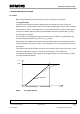
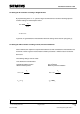
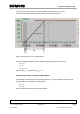
Then, the system step response is recorded with the curve plotter from 0 to 100%.
For systems that tend to overshoot, 90% should be assigned as step value.
Tu Tg
Turning Point
Setpoint
System step response for T
u
-T
g
approximation
After the inflectional tangent is drawn in the figure, the following values can be read:
T
u
= 0.7s
T
g
= 7s
1.0 * K
S
= 1.0
The result is K
S
= 1.0 and the ratio T
g
/K
S
= 7s.
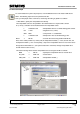
Setting the PI controller according to Ziegler-Nichols
The following controller parameters result with the values T
u
-T
g
approximation, and the rules for
controller adjustment according to Ziegler-Nichols:
K
PR
= 9
T
N
= 2.3s
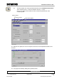
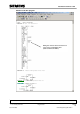
These controller parameters are transferred to DB41.
Preface Fundamentals Discontinuous Action Controller Controller Block (S)FB41 Setting the System Appendix
B3
Issued: 02/2008 Control Engineering with STEP 7