Deckblatt Model Predictive Control including integral transfer functions SIMATIC PCS 7 Application Example April 2010 Applikationen & Tools Answers for industry.
Industry Automation and Drives Technologies Service & Support Portal This article is taken from the Service Portal of Siemens AG, Industry Automation and Drives Technologies. The following link takes you directly to the download page of this document. http://support.automation.siemens.com/WW/view/en/42200753 If you have any questions concerning this document please e-mail us to the following address: Copyright Siemens AG 2010 All rights reserved online-support.automation@siemens.com MPC Level V 1.
Warranty and Liability Warranty and Liability Note The Application Examples are not binding and do not claim to be complete regarding the circuits shown, equipping and any eventuality. The Application Examples do not represent customer-specific solutions. They are only intended to provide support for typical applications. You are responsible for ensuring that the described products are used correctly.
Table of Contents Table of Contents Warranty and Liability ................................................................................................. 4 1 Preface ................................................................................................................ 6 2 Introduction........................................................................................................ 7 2.1 2.2 2.3 2.3.1 2.3.2 2.3.3 2.3.4 3 Stabilization of Unstable Control Loops .......................
Preface 1 Preface Objective of the Application The area of application of the model predictive controller provided in SIMATIC PCS 7 (function block ModPreCon and MPC respectively) is restricted by the following fact: The control algorithm only works for stable processes with a step response settling to a constant value in a finite time horizon. If the process is not stable or shows an integral action (e.g.
Introduction 2 Introduction 2.1 Basic Principles of Model Predictive Control A general overview of model predictive control is provided by the White Paper “How to improve the Performance of your Plant using the appropriate tools of SIMATIC PCS 7 APC-Portfolio?” https://pcs.khe.siemens.com/efiles/pcs7/support/marktstudien/WP_PCS7_APC_EN .pdf The application note including the basic principles of the MPC can be found here: http://cache.automation.siemens.
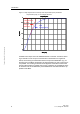
Introduction Figure 2-1 Step response of a control loop with compensation (blue) and without compensation (red), i.e. with integral behaviour. Step Response 3 whithout compensation, i.e. ohne with integral Ausgleich behaviour 2.5 with mit compensation Ausgleich Amplitude 2 1.5 1 Copyright Siemens AG 2010 All rights reserved 0.5 0 0 10 20 30 40 50 60 70 80 90 100 Time (sec) Unstable control loops cannot be stabilized without a controller.
Introduction 2.3 Examples of Unstable Control Loops 2.3.1 Level Control If the level of a tank with continuous feed is to be controlled via an adjustable drain as actuator (e.g. pump or valve with or without flow control), the control loop shows integrating behaviour. An equilibrium condition of the level only exists if the drain is exactly equal to the feed. The level permanently decreases until the tank is empty, if the drain is increased stepwise starting at this equilibrium condition.
Introduction feed water tanks. There are different objectives for level control according to the plant context [also see Related Literature /2./]: Keep level constant (exactly at the set point) – important for levels directly influencing the process; disturbances are passed through to the output (drain). Keep level as small as possible – if “dead volume” and inventory are undesirable.
Introduction 2.3.3 Position Control The control loop shows integrating behaviour if the position of mechanical parts is controlled and the speed of the actuator is available as manipulated variable. An "equilibrium condition" without move in the position only exists for a speed equal to zero. The valve actuator is a common example for position control in process plants. However, the valve position controllers are mostly integrated in the corresponding actuators and hence not an issue for the DCS.
Stabilization of Unstable Control Loops 3 Stabilization of Unstable Control Loops Regarding the stabilization of unstable control loops, integral processes and monotone unstable or oscillating unstable processes have to be distinguished. In general only an analysis in frequency domain is helpful for oscillating control loops. As an example, displacements of unstable poles to the stable domain can be examined using root locus analysis [also see Related Literature /3./].
Stabilization of Unstable Control Loops The behaviour of an integrating process g i s ki can be described by s t1 s 1 two parameters: The maximal gradient ki of the response to a unit-step (of height one) The delay time t1 needed by the process to reach its maximal gradient after a step in the manipulated variable (intersection point of the tangent with the base line in Figure 3-1) The transfer function of the closed loop including a proportional-only controller k s k p (kp is the p
Stabilization of Unstable Control Loops 3.2 PID Tuner The PCS 7 PID tuner can be used for integral processes without problems if at least one stable controller parameterization is already available.
Configuration of MPC with Slave Controller 4 Configuration of MPC with Slave Controller 4.1 Starting Point The starting point is the standard connection of the MPC with its actuators. The structure of the following example corresponds to the control of product quality (CV1) and level (CV2) in a reactor as mentioned in section 2.3.4. However, this example is not a realistic simulation of a real reactor.
Configuration of MPC with Slave Controller Figure 4-2 Signal flow chart of MPC with subordinated stabilizing PID controller for the integral main transfer function g22 g11 CV1 CV2 ModPreCon . g12 MV1 MV2 g21 PI Copyright Siemens AG 2010 All rights reserved CV2 LIC CV2 g22 The slave controller stabilizes the control variable CV1 in general. The integral effect of the main transfer function g22 is compensates as well as the integral effect of the coupling transfer function g21.
Configuration of MPC with Slave Controller Copyright Siemens AG 2010 All rights reserved Figure 4-3 Connection of MPC and slave controller MPC Level V 1.
Configuration of MPC with Slave Controller 4.3 Commissioning The parameterization of the controller and the commissioning is done „from interior to exterior” as in any cascade control. First the slave controller is tuned (see chapter 3) and switched to automatic mode. Afterwards the slave controller is switched to cascade mode and the master controller is parameterized.
Simulation Example 5 Simulation Example The simulation example was generated from a copy of the plant section ModPreCon of the APL_Example_EU, by introducing an additional integral block after the transfer function Proc662. Copyright Siemens AG 2010 All rights reserved Figure 5-1 Modified process simulation of the example project; the inserted integrator is marked in blue MPC Level V 1.
Simulation Example Copyright Siemens AG 2010 All rights reserved Figure 5-2 OS picture of the example project Despite the interaction between both manipulated variables MV1 and MV2 and the integral action of MV2 on PV2, both control variables PV1 and PV2 of the master controller can be controlled to their given set points independently of each other, which is a success of the described control concept. A “crosstalk” between the interacting control loops can mostly be avoided, e.g.
Conclusion 6 Conclusion Copyright Siemens AG 2010 All rights reserved The area of application of the model predictive controller embedded in SIMATIC PCS 7 is extended clearly by the described stabilization of unstable sub control loops with the help of a slave proportional-only controller. A typical application is an MPC where one controlled variable is the level of a tank, reactor, etc. MPC Level V 1.
Related Literature 7 Related Literature 7.1 Bibliography This list is not complete and only represents a selection of relevant literature. Tabelle 7-1 Titel 7.2 /1/ Krämer, S. Auslegung von Standreglern in der verfahrenstechnischen Praxis. DechemaSeminar „Prozessregelungen – von den Grundlagen zu Advanced Control“, Sep. 2008. /2/ Cheung, Tak-Fai und William L. Luyben Liquid-Level Control in Single Tanks and Cascade of Tanks with Proportional Only and Proportional-Integral Feed-back Controllers.
History 8 History Tabelle 8-1 Version 04.’10 Modifications First version Copyright Siemens AG 2010 All rights reserved V1.0 Date MPC Level V 1.