SINVERT 350, SINVERT 420 and SINVERT 500 TL Operating Manual – 11/2009 SINVERT Answers for environment.
Photovoltaic SINVERT Introduction 1 Description 2 Hardware operation 3 Alarm and fault messages 4 Support 5 SINVERT 350, SINVERT 420 and SINVERT 500 TL
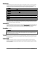
Safety instructions These Operating Instructions contain information which you should observe to ensure your own personal safety as well as to protect the product and connected equipment. The notices referring to your personal safety are highlighted in the manual by a safety alert symbol. Notices referring only to equipment damage have no safety alert symbol. Warnings are shown in descending order according to the degree of danger as follows.
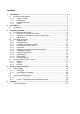
Contents 1 2 3 4 5 Introduction ................................................................................................................... 6 1.1 About this documentation........................................................................................ 6 1.1.1 Scope of validity .............................................................................................. 6 1.1.2 Target group....................................................................................................
Tables Table 3-1 Pin assignment X5 (SUB-D 9-pin/ RS422 for PPsolar) ........................................... 13 Table 4-1 Alarm and fault messages................................................................................. 27 Table 4-2 ISO fault .......................................................................................................... 30 Table 4-3 Fault 0 .............................................................................................................
Introduction 1.1 About this documentation 1 Introduction 1.1 About this documentation This manual will provide you with guidance in the use of SINVERT PV inverters. It provides you with a detailed overview of all the information you need to know about SINVERT PV inverters. We have checked that the contents of this document correspond to the hardware and software described. However, since deviations cannot be precluded entirely, we cannot guarantee full consistency.
Introduction 1.
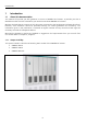
Description 2.1 Application 2 Description 2.1 Application The SINVERT PV inverter is a fully assembled, ready-to-connect inverter unit for PV installations. 1 2 3 Figure 2-1 Overview of PV system 1 The inverter transforms the DC voltage produced by the PV modules into an AC voltage. 2 The AC output voltage is transformed to the grid voltage by a medium-voltage transformer. 3 The PV solar system can thus be connected to the medium-voltage grid.
Hardware operation 3.1 Commissioning the inverter 3 Hardware operation 3.1 Commissioning the inverter Commissioning an installation requires certain switching operations to be performed. This type of work must always be undertaken by qualified, properly trained personnel. Failure to perform switching operations correctly can result in significant property damage and serious physical injury. The components described in this manual operate at hazardous voltages and currents.
Hardware operation 3.1 Commissioning the inverter 3.1.2 Switching off and disconnecting the power supply The entire system must be disconnected from the power supply before test and maintenance work can be carried out in the containers. Carry out these tasks in the sequence given below: 1. 2. 3. 4. Press the OFF key briefly on the control panel of every inverter. For reasons of safety, also press the Fast Stop button (if one is installed) in the inverter room.
Hardware operation 3.1 Commissioning the inverter 3.1.3 Switching on The inverter is switched on in the same way as it is switched off, but in the reverse sequence. 1. 2. 3. 4. 5. 6. 7. 8. 9. 10. 11. 12. Check that all connections have been made correctly (including polarity). Switch on the junction boxes in the PV field. Switch on the external power supply for the medium-voltage switchgear. Switch on the external power supply for the inverter container. Close the medium-voltage breaker.
Hardware operation 3.2 Operating the inverter 3.2 Operating the inverter 3.2.
Hardware operation 3.
Hardware operation 3.2 Operating the inverter 3.2.2 Operating mode You can choose between modes "Automatic" and "Test". In Test mode, you can adjust the DC voltage manually. In Automatic mode, the inverter determines the Maximum Power Point (MPP) automatically. It also displays currently active fault messages. To select Test mode, turn the keyswitch to the "TEST" position. To select Automatic mode, turn the keyswitch to the "AUTO" position. 3.2.
Hardware operation 3.2 Operating the inverter 3.2.5 Fault reset You can reset a fault by turning the keyswitch from "AUTO" to "TEST" and back to "AUTO" or vice versa. If the inverter has been disabled due to a fault, it can now be activated again. 3.2.6 Displaying currently active alarms and faults In Automatic mode, you can display the last ten alarm and fault codes. To do this, press the OFF key in Automatic mode for more than 3 seconds.
Hardware operation 3.2 Operating the inverter Maximum Power Point (LED "MPP") The power which can be generated by a PV system depends on the level of insolation and the temperature of the PV modules. The inverter control unit is equipped with a "Tracker" which automatically tracks the MPP (Maximum Power Point) of the PV field in Automatic mode. As soon as the inverter tracker has found the MPP, the LED "MPP" lights up.
Hardware operation 3.3 Communication with the inverter 3.3 Communication with the inverter Various possible methods of communicating with the inverter are presented below. 3.3.1 WEB’log WEB’log is generally used to log inverter data, i’checker data and meteorological data which has been recorded while the inverter is in operation. This data can be represented graphically in an Internet portal. In systems with WinCC, WEB’log serves as an interface for the i'checker sensors. 3.3.
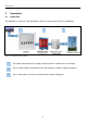
Hardware operation 3.3 Communication with the inverter Gray: Blue: Green: Red: No information available about the system components System components are ready; no energy flowing System components are running; energy is flowing System components are malfunctioning Figure 3-5 System Diagram PPsolar The System Diagram contains the electrical data of the entire PV installation plus all important information about the operating status of the system (voltage, current, output, frequency).
Hardware operation 3.3 Communication with the inverter The Control Panel (Figure 3-6) contains the same display and control elements as the control panel of the SINVERT PV inverter.
Hardware operation 3.3 Communication with the inverter The Oscilloscope function (Figure 3-7) enables you to record data in two channels and to print output voltages, output currents, inverter currents and the PV generator voltage. The right to use this special function is reserved for Siemens customer service personnel. The trigger control function enables you to choose the events which will trigger measured data recordings.
Hardware operation 3.3 Communication with the inverter The Process Data window (Figure 3-8) displays information about the inverter. For the sake of better clarity, the window is divided into a number of panes. You can specify the number of panes and their content in a configuration file. In the default configuration, the content of the individual panes is as follows: Device Information The device information box displays the software version of the CU4 control unit.
Hardware operation 3.3 Communication with the inverter Actual Value Summary The window with the overview of actual values displays a summary of key data of the PV system. You can alter data (e.g. reactive power transfer from SINVERT to the three-phase AC grid) in this window when it is active. Actual values The Actual Values window displays all electrical data of the PV system, as well as information about weather and insolation. You can alter data (e.g.
Hardware operation 3.3 Communication with the inverter The Data Storage window (Figure 3-9) is used to start, stop and configure the data archiving function of the PowerProtect solar system. The data to be archived, the scan rate, the data length and archiving path are specified in this window. The scan rate (tscan > xxs) and the data length, i.e. the period for which the data will remain stored in the archive file, can be freely selected (tfile > 1 day).
Hardware operation 3.3 Communication with the inverter Energy The Energy window displays all the available energy data of the PV system. Check the boxes for the values that you want PowerProtect solar to archive.
Hardware operation 3.3 Communication with the inverter The Analysis window (Figure 3-10) displays the data archived by PowerProtect solar. The data are saved in Microsoft Access database format by the data storage function. You can access this information at any time, even while the archiving function is active. The Analysis window also provides functions for printing out data, copying data to the Windows clipboard or editing data in MS Excel or Access.
Alarm and fault messages 4.1 Fault handling 4 Alarm and fault messages 4.1 Fault handling 4.1.1 Fault types There are two different types of fault, i.e. plant faults and operational faults. Plant faults are caused by malfunctioning of an inverter component, while operational faults occur as a result of unexpected external influences or logical conditions of the control software.
Alarm and fault messages 4.2 Alarm and fault messages 4.2 Alarm and fault messages The table below provides an overview of alarm and fault messages supplied on the inverter. Table 4-1 Alarm and fault messages No.
Alarm and fault messages 4.
Alarm and fault messages 4.2 Alarm and fault messages 4.2.1 Faults – Causes/diagnostics/remedial measures First acknowledge the fault with the keyswitch on the control panel.
Alarm and fault messages 4.
Alarm and fault messages 4.2 Alarm and fault messages Table 4-3 Fault 0 (Alarm) General fault on transformer The hardware contact in the power unit has tripped. There is a defect in the inverter. Replace the affected components. Replace the drive. Condition Causes Measures Table 4-4 Faults 1 and 33 Message 1 (alarm): Inverter is signaling overtemperature, stage 1 Fault 33 (alarm): Inverter is signaling overtemperature, stage 2 An excessive heatsink temperature in the inverter has Condition been detected.
Alarm and fault messages 4.
Alarm and fault messages 4.2 Alarm and fault messages Table 4-9 Fault 36 (Alarm) AC contactor defective (no checkback), or Fast Stop button pressed There is no signal at input 11/12 of the CU (green Condition connector); transferred via Profibus to the S7; drive has received an ON command.
Alarm and fault messages 4.
Alarm and fault messages 4.2 Alarm and fault messages Table 4-13 Fault 43 (Alarm) Vce monitor has responded The CU has detected an inadmissible circuit voltage (voltage on semiconductor module between emitter and collector).
Alarm and fault messages 4.
Alarm and fault messages 4.
Alarm and fault messages 4.
Alarm and fault messages 4.
Alarm and fault messages 4.
Support 5.1 Contact addresses 5 Support 5.1 Contact addresses The support hotline for SINVERT can be reached via the contact methods listed below from Monday to Friday between 8 am and 5 pm CET: Phone: Fax: E-mail: Internet: +49 911 750-2211 +49 911 750-2246 sinvert-service.i-ia@siemens.com www.siemens.de/sinvert www.siemens.
Siemens AG Industry Sector, IA SE S PV P.O. Box 2355 90766 Fuerth GERMANY www.siemens.