SB Encased Systems Breakers 800A—5000A Frame Ratings Information and Instruction Guide
Circuit breaker indicators shown in this booklet are for illustration purposes only. Circuit breakers are to be installed in “Discharged” and “Open” positions only. IMPORTANT The information contained herein is general in nature and not intended for specific application purposes. It does not relieve the user of responsibility to use sound practices in application, installation, operation, and maintenance of the equipment purchased.
SB Encased Systems Breakers Table of Contents General Information 2-5 Description Stationary and Moveable Drawout Elements Electronic Trip Units for Siemens SB Encased Breakers 6-7 6 7 Frame Installation Instructions Stationary Drawout Element Movable Drawout Element Fixed Mounted 8-10 8 9 10 Installation Instructions Electronic Trip Unit Rating Plug 11-14 11 13 Operating Instructions Operating the SB Encased Systems Breaker Manipulating the Moveable Drawout Element 15-25 15 18 Internal Accessorie
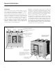
General Information Introduction Siemens SB Encased Systems Breakers bridge the performance gap between Molded Case Circuit Breakers (MCCB) and Low Voltage Power Circuit Breakers (LVPCB). Modern computer-aided design and manufacturing tools were used to effectively blend the technologies of the MCCB and LVPCB. This combination has resulted in a family of encased systems circuit breakers that exhibit the most desirable characteristics of each of the parent technologies.
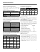
General Information Frame Sizes and Frame Ampere Ratings IEC 947-2 Ratings (SBS Units Only) SB breakers come in four frame sizes with MAX ratings ranging from 400A to 5000A. All frames are rated for 100% continuous operation.
General Information NOTE: For more information on other standard and optional trip unit features, see Siemens Electronic Trip Units for SB Encased Systems Breakers Information and Instruction Guide Bulletin IPIM-2203 and the Sentron Systems Breaker Energy Communicating Trip Unit Information and Instruction Guide Bulletin IPIM-2208. This patented construction provides a higher interrupting capacity within a smaller housing than can be achieved by more conventional construction.
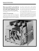
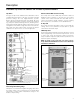
General Information Compact Size For space-limited installations, the 1200A and 2000A frames offer a common width of 15 1/2 inches, a common depth of only 12 1/8 inches, a common mounting footprint, and common bus center lines. This compact, shallow depth (even with drawout breakers) permits stacking of six 800A or 1200A breakers or four 2000A breakers in a standard switchboard. This packaging is made possible by the insulated-encased construction and thermal performance of the SB breaker.
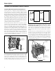
Description Stationary and Moveable Drawout Elements Simplified Minimum Depth Drawout Mechanism The two elements of a drawout constructed SB Encased Systems Breaker are the stationary drawout element and the moveable drawout element. The stationary drawout element mounts from the front or bottom into a standard switchboard. Bottom mounting flanges are provided for optional mounting arrangements. The moveable drawout element mounts onto the stationary drawout element’s two extension rails.
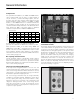
Description Electronic Trip Units For Siemens SB Encased Systems Breakers Trip Units Advanced True RMS Current Sensing Two types of trip unit are available for the SB breakers. The TL (standard) Trip Unit features a full range of industry standard protective settings.
Frame Installation Instructions Stationary, Moveable, and Fixed-Mounted Drawout Elements Installation instructions for systems breakers, trip units, and rating plugs are presented in this section. Installation instructions for accessories that may be installed in the field are presented in the Accessories section. Installing Drawout Constructed SB Breakers Drawout constructed SB breakers are designed to be installed from the front into a switchboard with a minimum width opening: 19 in.
Frame Installation Instructions Stationary, Moveable, and Fixed-Mounted Drawout Elements Installing the Moveable Drawout Element The outline drawings of the moveable drawout elements are located in the Outline Dimension Drawings section starting on page 36. Carefully uncrate the moveable drawout element and remove all packing material with the exception of the wire ties holding the racking pump handle in place.
Frame Installation Instructions Stationary, Moveable, and Fixed-Mounted Drawout Elements To correctly engage the moveable drawout element with the racking mechanism, the crank pins on the sides of the moveable drawout element must be in the Unlocked position as illustrated and the release lever must be in the Up position. During shipping and handling, the crank pins may have rotated out of position. If so, rotate them to the correct position.
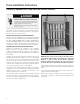
Installation Instructions Electronic Trip Unit Note: If you are installing a SB-EC Trip Unit, refer to the Information and Instruction Guide for this device (IPIM2208). To install the trip unit, remove the breaker’s front cover. This is done by removing the four recessed Phillips head screws in positions 2, 3, 6, and 7, as well as the four Phillips head screws in positions 1, 4, 5, and 8, which hold the front cover in place.
Installation Instructions Electronic Trip Unit Before attempting to install the trip unit, check the label on the side of the unit to make sure that it is the correct unit for the SB breaker. A built-in rejection scheme will prevent the installation of a trip unit into a breaker for which it is not intended. 4. Check label on side of trip unit. This scheme consists of two pins on the support plate on which the trip unit will set and two matching holes in the bottom of the trip unit.
Installation Instructions Electronic Trip Unit Rating Plug 8. Replace circuit breaker front cover. Replace the front cover. Then, replace the eight front cover screws. ! CAUTION Do not attempt to install a rating plug with the breaker Closed or Charged. Make certain breaker is Open and Discharged as shown above. Personal injury or mechanical damage may occur. Verify that breaker is Open before inserting or removing a rating plug.
Installation Instructions Rating Plug ! CAUTION Do not attempt to force an incorrect rating plug into a trip unit. Mechanical damage may occur. The receptacle in the trip unit has been keyed to prevent the insertion of an incorrect rating plug. 5. To replace the cover, bow it slightly in the middle and snap into place. 3. Check label on the rating plug. Check the rating plug label to verify that it is the correct plug for the trip unit.
Operating Instructions Operating the SB Encased Systems Breaker General Instructions Operating the SB Breaker Instructions for charging the stored energy mechanism, closing and opening the breaker, and positioning and rotating the moveable drawout elements of the drawout-constructed SB breakers are presented in this section. The trip unit’s standard test and monitoring functions are also presented.
Operating Instructions Operating the SB Encased Systems Breaker Discharged indicator points to Spring Charged. The charging handle returns to the stowed position when released. While manually charging the breaker with the charging handle, do not depress the Push-to-Close or Push-to-Open push buttons. If an optional electric motor operator is employed, the electric operator automatically recharges the stored energy mechanism when the breaker is closed.
Operating Instructions Operating the SB Encased Systems Breaker Discharging the Stored Energy Mechanism Without Closing the SB Breaker Discharging the energy in the stored energy mechanism without closing the breaker creates an abnormally high shock condition on the breaker. Avoid this procedure except for safety and/or emergency reasons. To discharge the energy, push and hold the Open pushbutton and then push the Close pushbutton.
Operating Instructions Manipulating the Moveable Drawout Element Manipulating the Moveable Drawout Element There are four positions of the moveable drawout element. These four positions are defined as Connected, Test, Unlocked, and Unlocked/Withdrawn. The connected position is the normal operating position of the breaker. In this position the primary stabs and secondary contacts are connected and the moveable drawout element is locked into position.
Operating Instructions Manipulating the Moveable Drawout Element Directional Shift Lever Racking Controls A built-in, low-force pump handle and two control levers are used to rack the moveable drawout element between the Connected, Test, and Unlocked positions. The directional shift lever determines the direction the movable drawout element will move when it is racked. The lever has three positions: racking-out, neutral, and racking-in.
Operating Instructions Manipulating the Moveable Drawout Element Racking Pump Handle Drawout Position Indicator A low-force pump handle is used to rack the moveable drawout element. The pump handle is an integral part of the racking mechanism, eliminating the need for an auxiliary racking device. If there is any resistance in returning the pump handle to the stowed position, set the directional shift lever to the neutral position. The racking pump handle can then be returned to the stowed position.
Operating Instructions Manipulating the Moveable Drawout Element Fully Withdrawn and Unlocked Positions To move the moveable drawout element from the Fully Withdrawn position to the Unlocked position, push toward the bus connections until the moveable drawout element hits a solid stop. The secondary disconnects on both sides of the moveable and stationary drawout elements will mate as the moveable drawout element moves into the Unlocked position.
Operating Instructions Manipulating the Moveable Drawout Element ! CAUTION To avoid damaging the racking mechanism, always pull the release lever before racking the moveable drawout element. Unlocked Position to Test Position Racking the moveable drawout element from the Unlocked position to the Test position engages the moveable drawout element with the stationary drawout element. The physical position of the moveable drawout element will be unchanged.
Operating Instructions Manipulating the Moveable Drawout Element ! CAUTION To avoid damaging the racking mechanism, always pull the release lever before racking the moveable drawout element. Test Position to Connected Position To rack the moveable drawout element from the Test position to the Connected position. 3. Pump the racking pump handle until the moveable drawout element is in the Connected position. 1. Push in the directional shift lever. This is the racking-in position. 4.
Operating Instructions Manipulating the Moveable Drawout Element ! CAUTION To avoid damaging the racking mechanism, always pull the release lever before racking the moveable drawout element. Connected Position to Test Position To rack the moveable drawout element from the Connected position to the Test position, ensure that the SB breaker is open. (If the breaker is closed and the release lever is moved downward to the interlock disengaged position, the breaker will trip.) 3.
Operating Instructions Manipulating the Moveable Drawout Element ! CAUTION To avoid damaging the racking mechnism, always pull the release level before racking the moveable drawout element. Test Position to Unlocked Position 4. Pump the racking pump handle until the moveable drawout element is in the Unlocked position. Racking the moveable drawout element from the Test position to the Unlocked position disengages the moveable drawout element from the stationary drawout element.
Internal Accessories Preliminary Installation Procedures NOTE: Refer to the separate SB Accessories Installation and Instruction Guide for information on Accessory Installation and ratings. Refer to the separate SB Trouble Shooting Guide for trouble-shooting tips. ! CAUTION Mechanism can cause severe injury when cover is removed. Before removing cover, push open button, push close button, and then push open button again.
Internal Accessories Preliminary Installation Procedures 3. Remove the breaker cover by first removing the four #10 Phillips head screws at the corners and the four 1/4” Phillips head screws in recesses in cover. 5. Remove the trip unit if installed, by removing trip unit retaining screw. 4. Remove cover. 6. Slide the trip unit up to clear the support bracket pins. 7. Remove the trip unit by pulling the trip unit away from the trip unit plug.
Internal Accessories Preparation For Installation of Internal Accessories Accessories The full family of accessories available for Siemens SB breakers are presented in this section. The accessories are divided into two groups. Group one consists of accessories installed in the front compartment of the circuit breaker (Internal Accessories). . ! CAUTION Install all accessories with the breaker Open and Discharged as shown above.
Internal Accessories Preparation For Installation of Internal Accessories Removing the Left and Right Drawout Mechanism Complete the following steps to remove the crankshaft. 5. Take off the left and/or right mechanism assemblies (as required) by removing the two, three or four 5/16-inch bolts and nuts on each side. 1. Remove the E-rings from the bar cap pin on each side. Note: e-ring may be located on outside of plate. *Note this location for reassembly. 2. Remove the bar cap pin from each side.
Internal Accessories Preparation For Installation of Internal Accessories 5. Install the bar cap pins through the bar caps and left and right mechanism assemblies with the head of the pins toward the center of the breaker. Note: Bar cap pin should be reinstalled on the side it was originally removed. 3. Install the crankshaft assembly by positioning the crank pin anywhere between the unlocked and connected positions as shown and lowering the crankshaft to the bottom of the slot.
External Accessories Siemens ACCESS Communications System data displays and trip unit configuration via Siemens SBWIN software. Remote open/close operation is also possible if a remote open/close relay is installed. Expansion Plug Breaker Type Frame Size Mounting Type SB ICCB 1200A, 2000A Fixed EPSBFMK Drawout EPSBDMK SB ICCB SB Breaker Communication All SB Circuit Breaker trip units feature two levels of communication: Zone Selective Interlocking and ACCESS System openprotocol communications.
External Accessories Siemens ACCESS Communications System 2. If multiple MT’s are used, the “Com” terminal from the first MT’s “SEABus Out” port must be connected to the “Com” terminal of the next MT’s “SEABus In” port on each MT being used. The MTCSB cable is used to connect an MTA or MTZ to an EPSB expansion plug via the SB breaker secondary terminal block or sliding disconnect. A. SB Breaker Zone Selective Interlocking (only) 3.
External Accessories Siemens ACCESS Communications System B. SB Breaker ACCESS Communications (with or without Zone Interlocking) 1. Standard type ‘TL’ switch-based trip unit Components Required: • Siemens type MTZ – one per 8 trip units • Siemens type EPSB expansion plug – one per trip unit, factory wired • Siemens type MTCSB cable – one per trip unit located on the breakers secondary control terminals to RS485(+), to RS-485(-), and to Shield/Common.
External Accessories Universal Test Kit (TS-31) General Information 7. Comply with the prompt to start the test. The test can require a few seconds or several minutes, depending on which procedure is running. NOTE: If the breaker trips during a test, reset it before continuing. The last setting entered into the TS-31appears in brackets on the second line of the display. If you do not want to change an existing setting, press ENTER. If you want to change a setting, type in the new setting and press ENTER.
Outline Dimension Drawing 1200A Stationary Drawout Element 21.82 9.56 5.82 2.75 2.94 2.38 .75 8.75 20.50 17.38 5.00 19.00 Front Cover 1.25 Lifting Points. Do Not Lift By Other Points 17.50 C L 18.50 Inside Cradle 5.00 .50 2X .54 4X Top Ø.228 Holes 4X Bottom 4X Top Ø.438 Optional Mounting Holes 4X Bottom Preferred Mounting Surface 26.46 See Detail A 15.86 15.37 Wire Path For Secondary Contacts 1.75 .85 2X 2.00 2X 1.00 2X 3.50 1.36 C L 2X 5.00 2X 3.62 4X Ø.
Outline Dimension Drawing 1200A Stationary Drawout Element 1.30 .44 3/8 -16 Bus Support Bolts Optional Rear Mounting Surface Detail A Scale 1/1 20.00 10.00 8.75 4X 1.00 12X Ø.281 Front Mtg. Holes Of Bus C L Stab 8.562 C L Of Bus Stab 2X 6.88 4X 5.50 2X .375 13.75 2X 1.00 4X 2.50 C L Rear View 36 Provide Clearance Holes For #8 - 32 Screws When Using Rear Flange Mounting Surface.
Outline Dimension Drawing 1200A Moveable Drawout Element C L C L 2.87 2.84 2.87 2.84 4X .59 2X .44 4.59 4.56 1.74 C L C L 2.13 .20 4.59 4.56 3X Ø 1.25 .94 .94 Front View Front Panel Cutout Minimum Clearance (Escutcheon Dimensions) 20.50 Overall 10.25 6.88 13.
Outline Dimension Drawing 1200A Moveable Drawout Element 15.75 Breaker Fully Withdrawn 16.00 .75 1.45 Breaker Test Position Front Cover Location Shown Provides Minimum Clearance With Breaker 7.75 15.50 C L Top View 21.82 10.31 7.82 Minimum Clearance Required For Breaker Rotation R 11.52 10.54 58° C L 36° .
Outline Dimension Drawing 1200A Fixed-Mounted 15.50 C L Ø.34 Holes Typ. 5.00 5.00 1.00 Typ. See Detail A 3.37 1.13 11.13 11.38 11.63 12.13 Top View .09 2.50 2.
Outline Dimension Drawing 1200A Fixed-Mounted 5.00 5.00 R .125 Typ. C L 6X 1.32 .50 .66 1.13 Front View 2X 5.50 C L 9.75 C L 12.00 .37 .75 14.00 .87 7.375 .375 C L 14.75 4X Ø .44 Mounting Holes For 3/8 - 16x23/4 (Min.) screws, use 2 flat washers, 1 lock washer and nut. Torque to 15 ft. lbs. max. C L 2X 2.84 4X .59 2X .44 12X .38 X .43 Slot C L 4.56 1.74 C L 2.87 2.13 2.87 .20 4.56 3X Ø 1.25 2X .94 4.59 Front View (Escutcheon Dimensions) 1.75 Typ. C L .50 Typ. 4.59 90° Max.
Outline Dimension Drawing 2000A Stationary Drawout Element 1.30 .44 3/8 -16 Bus Support Bolts Optional Rear Mounting Surface Detail A Scale 1/1 20.00 10.00 C L Of Bus Stab 8.75 8.562 Typically 16 places Ø .281 Front Mtg. Holes Of Bus C L Stab 4X 1.00 4X 8.50 4X 5.50 2X .375 2X 1.00 19.75 2X 2.50 2X 9.75 C L Provide Clearance Holes For #8-32 Screws When Using Rear Flange Mounting Surface.
Outline Dimension Drawing 2000A Stationary Drawout Element 21.82 9.56 5.82 2.75 2.94 Front Cover .75 2.38 1.25 8.75 17.50 19.00 5.00 Lifting Points. Do Not Lift By Other Points. C L 17.38 5.00 .50 2X .54 4X Top Ø .228 Holes 4X Bottom 4X Top 4X Bottom Ø .438 Optional Mounting Holes Top View Preferred Mounting Surface 26.46 See Detail A (Page 41) 15.86 15.37 1.75 Wire Path For Secondary Contacts. .85 2X 4.00 2X .88 2X 7.50 8X Ø .438 C L 2X 3.62 1.36 2X 7.12 2X 2.
Outline Dimension Drawing 2000A Moveable Drawout Element 15.75 Breaker Fully Withdrawn 16.00 .75 1.45 Breaker Test Position Front Cover Location Shown Provides Minimum Clearance With Breaker 7.75 15.50 C L Top View 21.82 10.31 7.82 Minimum clearance required for breaker rotation R 13.50 12.14 58° C L .
Outline Dimension Drawing 2000A Moveable Drawout Element 44
Outline Dimension Drawing 2000A Fixed Mounted 15.50 C L 7.75 5.00 .09 5.00 .75 Typ. See Detail A 2.76 2.375 3.37 1.13 Detail A 11.13 C L 11.38 2X 2.84 11.63 12.13 4X .59 2X .44 C L 2.13 C L 4.56 1.74 .20 4.56 2.87 2.87 3X Ø 1.25 2X .94 24 Ø .39 Holes 1.75 Typ. 4.59 1.75 C L .88 2X 7 .12 4.59 90° Max. C L Front Panel Cutout Minimum Clearance 2X 2.50 7.82 Handle Clearance Rotation 2.
Outline Dimension Drawing 2000A Fixed Mounted C L 5.00 5.00 .75 Typ. 1.50 Typ. Mounting Holes 4X Ø .44 1.50 For 3/8 -16x23/4 (Min.) screws, use 2 flat washers, 1 lock washer and nut. Torque to 15 ft. lbs. max. 4X 5.50 2X 6.375 2X 8.375 C L C L 16.75 Front View 2.75 24 Ø .40 Holes 7.375 C L 14.75 R .125 Typ. 2.25 C L 9.75 Front View .75 14.00 15.
Outline Dimension Drawing 3200A, 4000A, and 5000A Stationary Drawout Element 23.28 7.30 Stationary Drawout Element Top View Dimensions 3.00 9.50 4.75 2.75 .75 2X 1.25 Frame Size Location 3200 4000/5000 A B C D E 20.36 5.00 17.38 18.50 21.50 28.34 7.50 25.38 26.50 29.50 4.00 .25 Lifting Points. Do Not Lift By Other Points. B A C E D Inside Cradle B .50 3200 Ampere Bus Configuration 6X Top Ø.438 Mounting Holes 6X Bottom 4X Top Ø.228 Holes 4X Bottom Front Cover Top View 1.75 .
Outline Dimension Drawing 3200A, 4000A, and 5000A Stationary Drawout Element C B A 16X Ø .281 Front Mtg. Holes 4X 15.00 35.00 4X 8.75 2X 17.50 4X 5.00 4X 4.00 4X 7.50 Rear View Stationary Drawout Element Rear View Dimensions Frame Size 48 Location 3200 4000/5000 A B C 2X 8.75 2X 10.25 20.50 2X 12.75 2X 14.25 28.
Outline Dimension Drawing 3200A, 4000A, and 5000A Moveable Drawout Element 16.00 .75 14.73 Breaker Fully Withdrawn 1.61 Breaker Test Position A B .50 3200 Ampere Bus Configuration Top View Moveable Drawout Element Top View Dimensions Frame Size 23.28 Location 3200 4000/5000 A B 7.50 15.00 11.50 23.00 15.15 7.76 2X 3.
Outline Dimension Drawing 3200A, 4000A, and 5000A Moveable Drawout Element Of Breaker Of Breaker 8.28 2.87 8.28 2.87 5.71 5.71 Of Breaker 3.45 Of Breaker 3.45 Front Panel Cutout Minimum Clearance Note: Not drawn to scale Optional Panel Cutout (For Trip Unit and Label Information) Note: Not drawn to scale A Overall 2.84 2.84 4X .59 B 2X .44 4.56 1.74 2.13 17.50 .20 4.56 3X Ø 1.25 .94 35.00 Overall .
Outline Dimension Drawing 3200A Fixed-Mounted 4.91 5.69 3.98 4.54 10.25 9.13 R .12 Typ. R .12 Typ. .75 14.00 Front View (Escutcheon Dimensions) 15.12 .25 1.00 Typ. 1.25 Typ. 1.12 .75 1.75 4.00 Typ. 1.87 16.75 8X Ø.56 .75 .75 1.75 5.00 Typ.
Outline Dimension Drawing 3200A Fixed-Mounted 52
Outline Dimension Drawing 4000A and 5000A Fixed-Mounted 8.91 5.68 R .12 Typ. 3.98 4.54 10.25 9.13 R .12 Typ. 3.50 16.50 Front View (Escutcheon Dimensions) 1.25 Typ. 5.00 26.00 .75 2.75 22.50 3.50 1.75 1.00 3.
Outline Dimension Drawing 4000A and 5000A Fixed-Mounted 23.50 20.00 12.50 5.00 .50 Typ. 1.50 Typ. .87 .63 11.13 11.38 11.63 12.13 12.75 Top View 21.25 15.00 7.50 4.00 30X Ø .41 Holes 2.00 2.75 1.75 3.50 3.00 11.00 20.50 22.50 27.50 3.00 4.75 5.00 .38 22.75 Front View 54 8X Ø .44 Mounting Holes For 3/8 -16 x 2 3/4 (Min.) Bolts. Use 2 Flat Washers, 1 Lockwasher and Nut. Torque to 15 lb. Max.
Electrical Schematics RT= Right Top Secondary Terminals on Breaker. Bell Alarm Reset Switch Electronic Bell Alarm Types SBDMR and SB4DMR + – Control Power TRIP ALARM 60VA Max. 1.25A Max. 150VDC/2000VAC Max.
Electrical Schematics Undervoltage Release Connection Monitored + Source – UVR+ UVR Coil UVR– DC Undervoltage Release External Connections Internal Breaker Connections DC Undervoltage Release Solenoid Schematic Monitored Source AC Undervoltage Release Schematic UVR Resistor If Needed UVR Internal Breaker Connections External Breaker Connections AC Undervoltage Release Solenoid Schematic 56 UVR Coil
Electrical Schematics Control + Power Supplied by Customer – Coil+ Shunt Trip Coil “B” Type Clearing Switch NC Coil - (Common) COM NO Supplied by Customer Remote Open-Closed Indication Shunt Trip Shunt Trip Schematic Auxiliary Switch 4 Note: Auxiliary swtiches 1A, 1B, 2A, 2B, 3A, 3B and 6A, 6B may be ordered as 8 normally open contacts or 8 normally closed contacts optionally.
Electrical Schematics 57A
Electrical Schematics "A" PHASE "C" PHASE "B" PHASE "N" PHASE X1 + X2 - TRIP UNIT NEUTRAL SENSOR + LEFT NOTE: TRIP UNIT PLUG SHOWN AS VIEWED FROM FRONT OF BREAKER. POLE + 4 8 12 16 20 24 28 32 CENTER 36 POLE NOTE: ELECTRONIC ALARM SWITCH, REMOTE INDICATOR PANEL LOCAL LOAD MONITOR RELAY, 4 AND REMOTE INDICATOR PANEL 3 7 11 15 19 23 27 31 35 2 6 10 14 18 22 26 30 34 1 5 9 13 17 21 25 29 33 2 ARE MUTUALLY EXCLUSIVE.
Electrical Schematics Electric Motor Operator SOLENOID ASSEMBLY AFTER TIGHTENING SOLENOID SCREWS, ALIGN LINKAGE WITH SOLENOID PLUNGER AND TIGHTEN SET SCREW AGAINST SHAFT. 11 HEAT SHRINK 13 15 16 6 LT 2 ASSEMBLY NO. 121523XXX PCB MCU ASSY #410986A00 PWB PWR ASSY #4109XXXXX XXXXXX LT3 LT1 LT2 8 Circuit Breaker Accessory 965D Listed SBEO24 15 R 11 -5 13 Cat. No. 3 LT Electric Operator LT5 Siemens Energy & Automation Inc.
Electrical Schematics Electric Motor Operator Electric Motor Operator Schematic THIS WIRE IS USED WHEN CCX IS INSTALLED. ELECTRIC OPERATOR CCX CLOSING COIL THIS WIRE IS USED WHEN CCX IS NOT INSTALLED. CUSTOMER SUPPLIED EXTERNAL CONTACT (SHOWN) (CCX) CCX MOTOR ELECTRIC CLOSE INTERLOCK OPTION (CCX) - NO AVAILABLE AS FACTORY INSTALLED OPTION ONLY. CONTROL POWER SWITCH "B" COM NC 120 W MAX. 2 AMPS MAX. 250 VDC/200VAC MAX.
Accessory Ratings Motor Operator Current Draw Supply Voltage Shunt Trip Ratings Motor Rating (Amperes) 120VAC 24VDC 48VDC 125VDC Catalog Number 3 3 3 3 Electrical Data for Remote Close Solenoid Coil Voltage Inrush Current (Amperes) 120VAC (60 Hz) 9.4A SB4RCS120 SBRCS120 24V DC 48V DC 125V DC 20.0A 10.3A 3.6A SB4RCS24, SBRCS24 SB4RCS48, SBRCS48 SB4RCS125, SBRCS125 Catalog Number Switch Contact Ratings Supply Voltage Ampere Rating 120VAC 240VAC 480VAC 24VDC 125V DC 10.0A 10.0A 6.0A 3.0A 0.
SB Solenoid Coil Resistances SHUNT TRIP SOLENOID: Shunt Trip Plunger O.D. = 0.310 inch +/– 5% @ 20 degrees C 12 VDC – 3.6 ohms 120 VAC – 79.6 ohms 24 VDC – 14.2 ohms 240 VAC – 380 ohms 48 VDC – 55 ohms 480 VAC – 1163 ohms 125 VDC – 370 ohms Shunt Trip Plunger O.D. = 0.437 inch +/– 10% @ 20 degrees C 12 VDC – 4.
Siemens Energy & Automation, Inc. Power Distribution Infrastructure Division 3333 Old Milton Parkway Alpharetta, GA 30005 © 2001 Siemens Energy & Automation, Inc. Siemens is a registered trademark of Siemens AG. Specifications are subject to change without notice. For Nearest Sales Office 1.800.964.4114 www.sea.siemens.com/sales For Production Information www.sea.siemens.com/power Order No.